Visualization of radio frequency coverage

a radio frequency and coverage technology, applied in the field of radio frequency (rf) coverage planning, can solve problems such as difficulties in solving coverage problems and unexpected coverage loss

Inactive Publication Date: 2014-03-04
HEWLETT-PACKARD ENTERPRISE DEV LP
View PDF0 Cites 3 Cited by
  • Summary
  • Abstract
  • Description
  • Claims
  • Application Information

AI Technical Summary

Problems solved by technology

This method of visualization has a number of problems.
When used for planning purposes, this can lead to unexpected coverage loss when the vertical or elevation pattern of the antenna is important.
When used for monitoring, the lack of full three dimensional antenna pattern visualization can lead to difficulties in solving coverage problems.

Method used


Image

  • Visualization of radio frequency coverage
  • Visualization of radio frequency coverage
  • Visualization of radio frequency coverage

Examples


Embodiment Construction

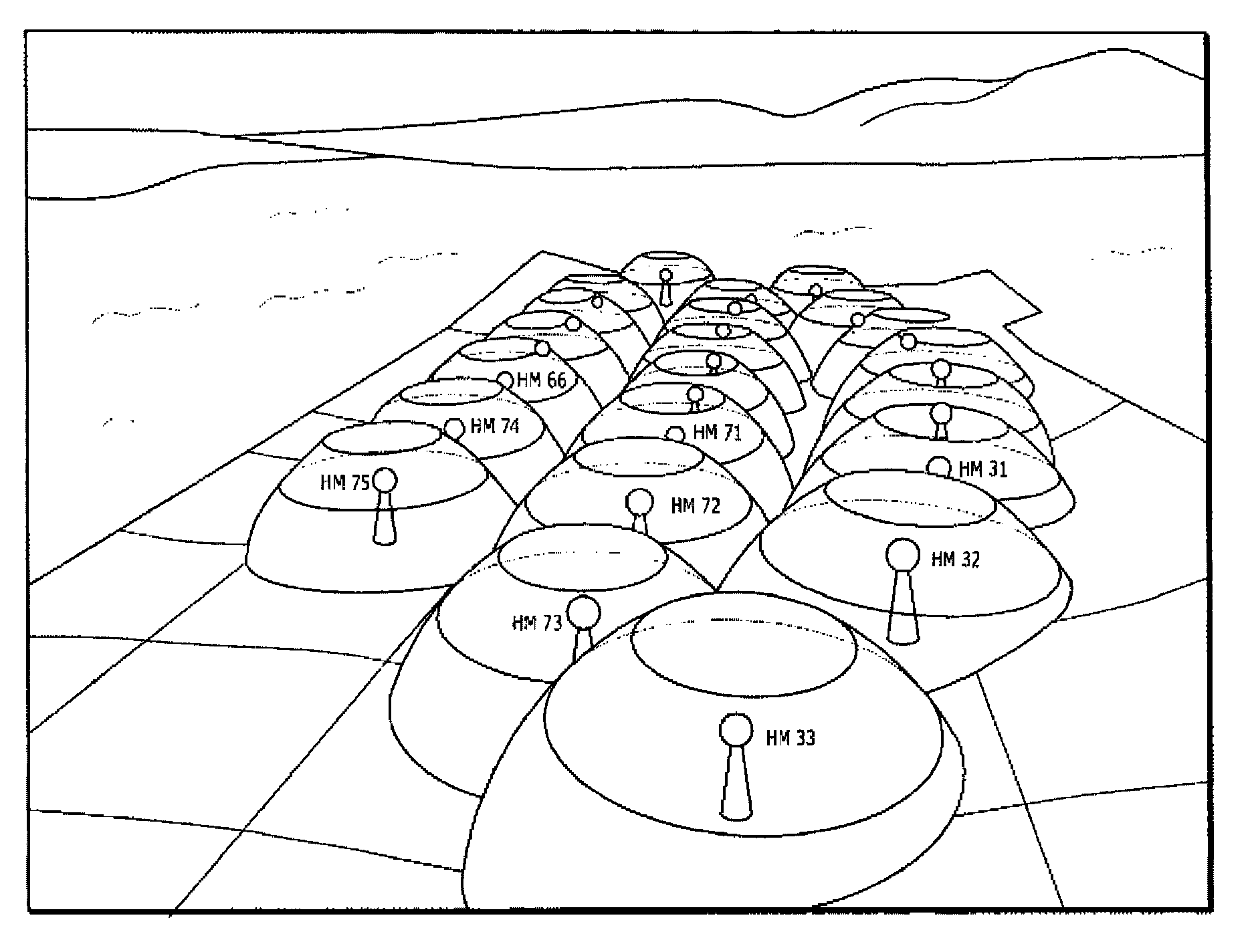
[0020]Embodiments of the invention relate to preparing and displaying RF coverage models by mapping or using a Geographic Information System (GIS). According to one embodiment of the invention, a base unity coverage model is produced using the three dimensional pattern of an antenna. This three dimensional base unity coverage model is linear in nature and is independent of antenna gain, radio parameters such as transmit power and receive sensitivity, and environmental factors such as signal absorption by trees. Since the base unity coverage model is linear, it can be scaled using linear scaling factors. These scaling factors may be based on antenna absolute gain, feedline parameters, radio parameters, regulatory requirements, and / or environmental factors, for example. The three dimensional coverage model can be directly viewed, and rapidly re-scaled along with other linear features such as distance in mapping and Geographic Information Systems (GIS).

[0021]According to the present in...


PUM


Abstract

Radio Frequency (RF) coverage models are visualized by displaying three dimensional unity scaled models of antenna performance in a Geographic Information System (GIS), Traditional logarithmic scaled antenna models are converted to linear models and stored as three dimensional representations which are placed and scaled using a GIS to visualize RF coverage.

Description

BACKGROUND OF THE INVENTION[0001]The present invention relates to radio frequency (RF) coverage planning, and more specifically, to methods for visualizing RF coverage.[0002]RF coverage planning assists the RF engineer in answering the question, where do I need to put antennas to provide a specified service level over a given area, or to answer the corollary question, what will my coverage be if I put antennas in the following locations?[0003]One skilled in the art of RF engineering can perform calculations and make coverage predictions. These predictions typically require information along the following lines to be available: radio characteristics such as transmit power and receive sensitivity, antenna radiation characteristics, transmission lines, and the medium through which the coverage must be planned.[0004]In a method typical of the prior art in displaying coverage based on antenna characteristics, the engineer first obtains antenna pattern information. This may be obtained fr...

Claims


Application Information

Patent Timeline
Patent Type & Authority Patents(United States)
IPC IPC(8): G06F17/10
CPCH04W16/18
Inventor VITEK, CLARK, A.
Owner HEWLETT-PACKARD ENTERPRISE DEV LP
Why Eureka
Try Eureka