

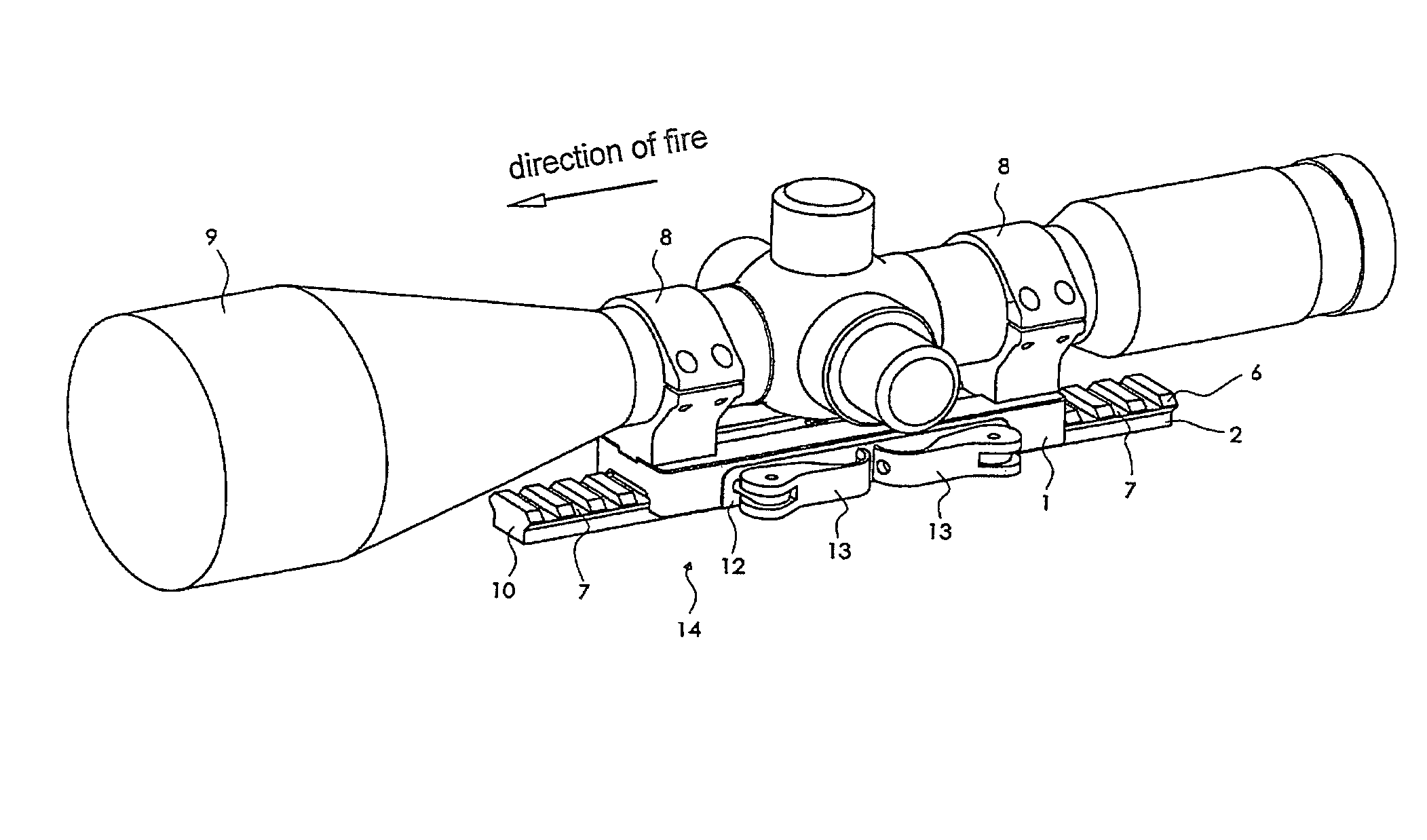
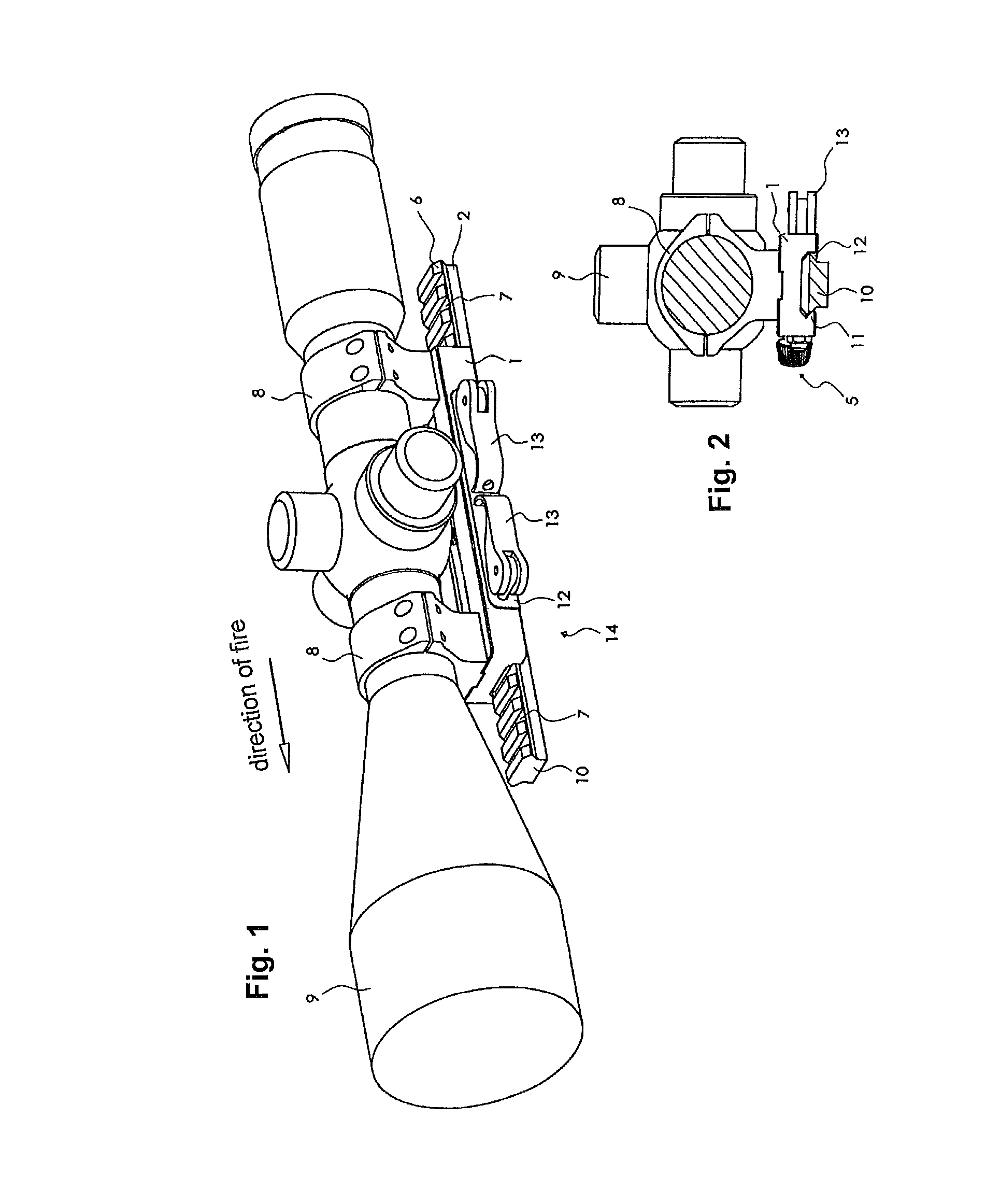
Device for mounting an additional device to a firearm
a technology for mounting an additional device and a firearm, which is applied in the direction of sighting devices, weapon components, cartridge extractors, etc., can solve the problems of unfavorable accurate positioning of recoil lugs in the transverse groove, unfavorable accurate positioning of recoil lugs, and unfavorable shooting accuracy
- Summary
- Abstract
- Description
- Claims
- Application Information
AI Technical Summary
Benefits of technology
Problems solved by technology
Method used
Image

Examples
second embodiment
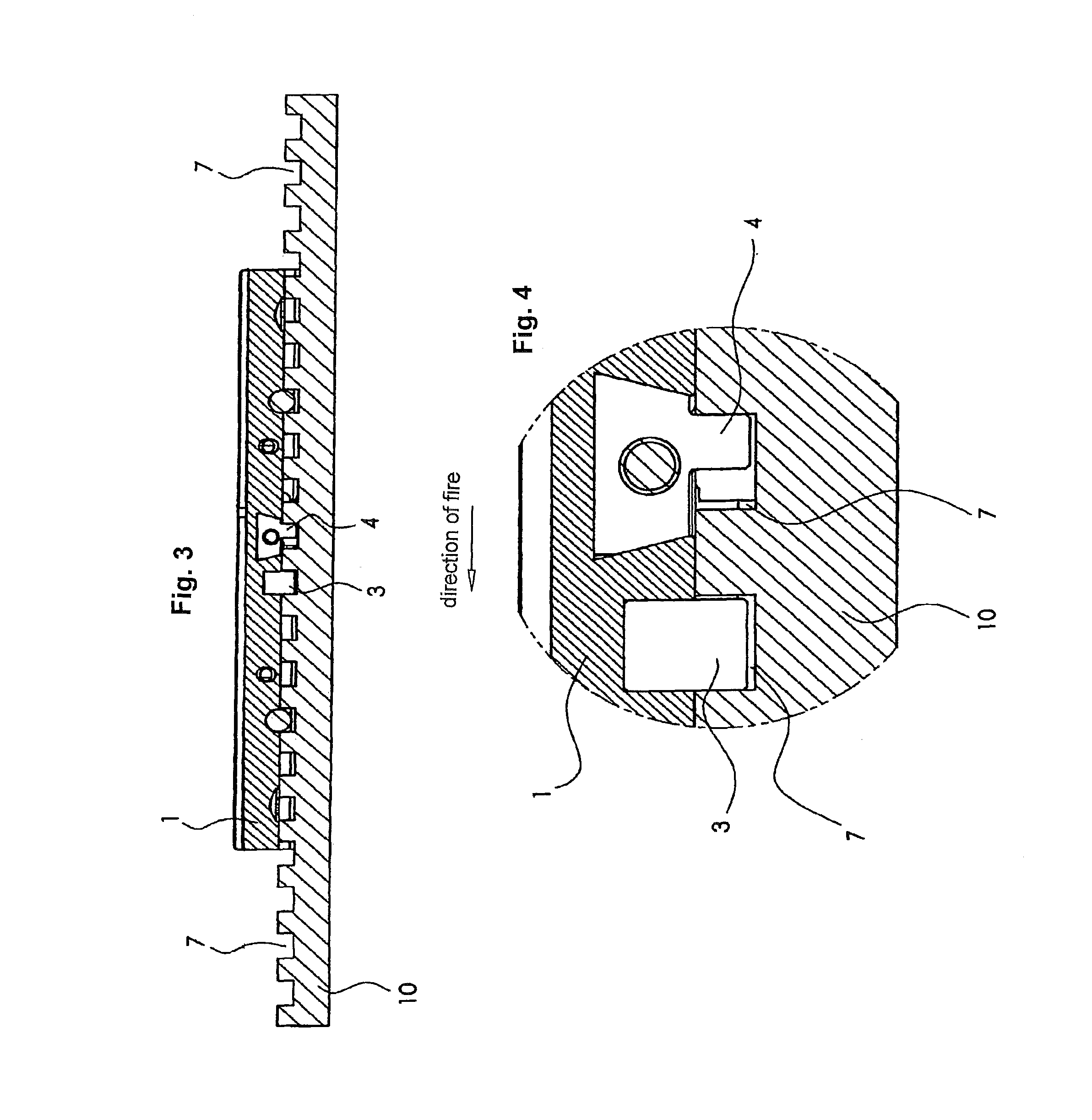
[0043]The structure of the tip-up mount (51) corresponds substantially to the tip-up mount (14) of the previous embodiment. Here a cylindrical pin (52) serves substantially as an additional stop, which is urged by the compression spring (53) against the wall (50) of one of the grooves (7) when seated on the Picatinny rail (10) and thus bring the recoil lug (3) into engagement forward in the direction of fire (see FIG. 10).
[0044]In a further embodiment, the pin (52) may have any other shape, for example substantially rectangular. Also, several springs can also be used. Also, instead of the compression spring, a leaf spring can be used.
[0045]The displacement of the pin (52) runs at an angle μ greater than 0° and less than 90°, preferably 15°. The contact surface (55) of the pin (52) compensates for this angle again. Thus, the contact surface (55) lies flat against the wall (50). To protect the edges of the groove (7), the pin (52) is provided with a radius (56) (see FIG. 11).
[0046]In ...
PUM
 Abstract
Description
Claims
Application Information