Dual-direction in-tank magnetic safety valve

a magnetic safety valve and in-tank technology, applied in the field of valves, can solve the problems of large pressure differential between the rear and front of the piston head, the liquid column in the piping presents an additional potential hazard, etc., and achieve the effects of preventing the loss of fluid from the tank, reducing the risk of leakage, and increasing the spatial distance relationship between the magnets

Active Publication Date: 2014-03-11
HASELOH PETER G +1
View PDF11 Cites 2 Cited by
  • Summary
  • Abstract
  • Description
  • Claims
  • Application Information

AI Technical Summary

Benefits of technology

[0010]The in-tank magnetic safety valve is also designed in such a way that should the valve itself be sheared off flush to the tank structure it will still prevent uncontrolled flow of fluid from the tank. This is due to the valve seat (or seats) and magnets being positioned inside the tank structure. As the magnets hold the valve in a normally-closed position and are protected from damage, the loss of fluid from the tank is prevented. The addition of the excess flow prevention feature of the valve may also be employed in this condition. As the valve is being sheared off, the piston is dragged forward by the departing piece before breaking the front of the piston off. This action engages the outer O-ring seal on the piston against the tapered outer valve seat in the main body, shutting off fluid flow.
[0011]The in-tank magnetic safety valve of the present disclosure accommodates any damage or irregularity between the in-tank magnetic safety valve and the source of vacuum, whether due to a piping break, filter damage, manual valve failure, or other cause. Because the valve requires a vacuum to open, any leakage caused by damage between the valve and the pump will result in a loss of vacuum. This loss of vacuum will cause the valve to revert to its normally-closed position or will prevent it from being activated at all. If a failure occurs at the lowest point in the system and the liquid column drains out, this causes a rapid change in differential pressure across the valve piston. This in turn causes the piston to move outward and contact the outer valve seat in the main body, thus sealing off the flow from the tank.
[0012]The in-tank magnetic safety valve also incorporates means for adjusting the spatial relationship between the magnets. The height of the fluid column will determine the final setting of the spatial relationship of the magnets; i.e., a tall tank will have a higher head pressure than a short tank. One of the magnets in the valve is installed inside an externally threaded holder. The rear of the valve body has internal threads that this magnet holder screws into. By screwing this magnet holder in or out, the spatial distance relationship between the magnets can be changed. By bringing the magnets closer together, magnetic attraction is increased and the valve will be able to hold back higher head pressures (as would be in the case for taller tanks). In the case of a shorter tank, the magnets are adjusted away from each other, thereby reducing magnetic attraction between them.
[0013]If installed in the bottom of a tank, the valve is adjusted until it will hold back a pressure equal to at least 150% of the fluid column acting against the smaller (inner) end of the piston in the valve. This reduces the amount of vacuum build-up that the pump or appliance needs to exert against the larger (outer) side of the piston in order to open the valve.

Problems solved by technology

This liquid column in the piping presents an additional potential hazard.
If the piping is sheared off at the appliance, the liquid column flows out of the piping, resulting in creation of a vacuum, which will open the valve.
Because the outward fluid flow in this scenario is uncontrolled (i.e., much more than what is usually called for by the appliance or pump), this creates a large pressure differential across the rear and front of the piston head.

Method used


Image

  • Dual-direction in-tank magnetic safety valve
  • Dual-direction in-tank magnetic safety valve
  • Dual-direction in-tank magnetic safety valve

Examples


Embodiment Construction

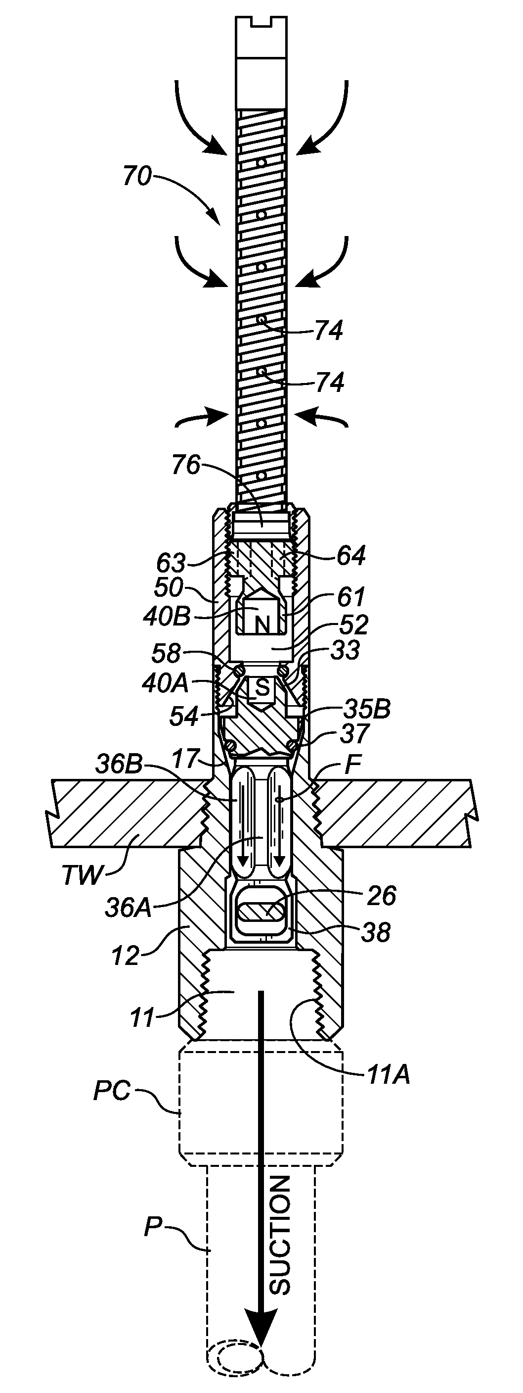
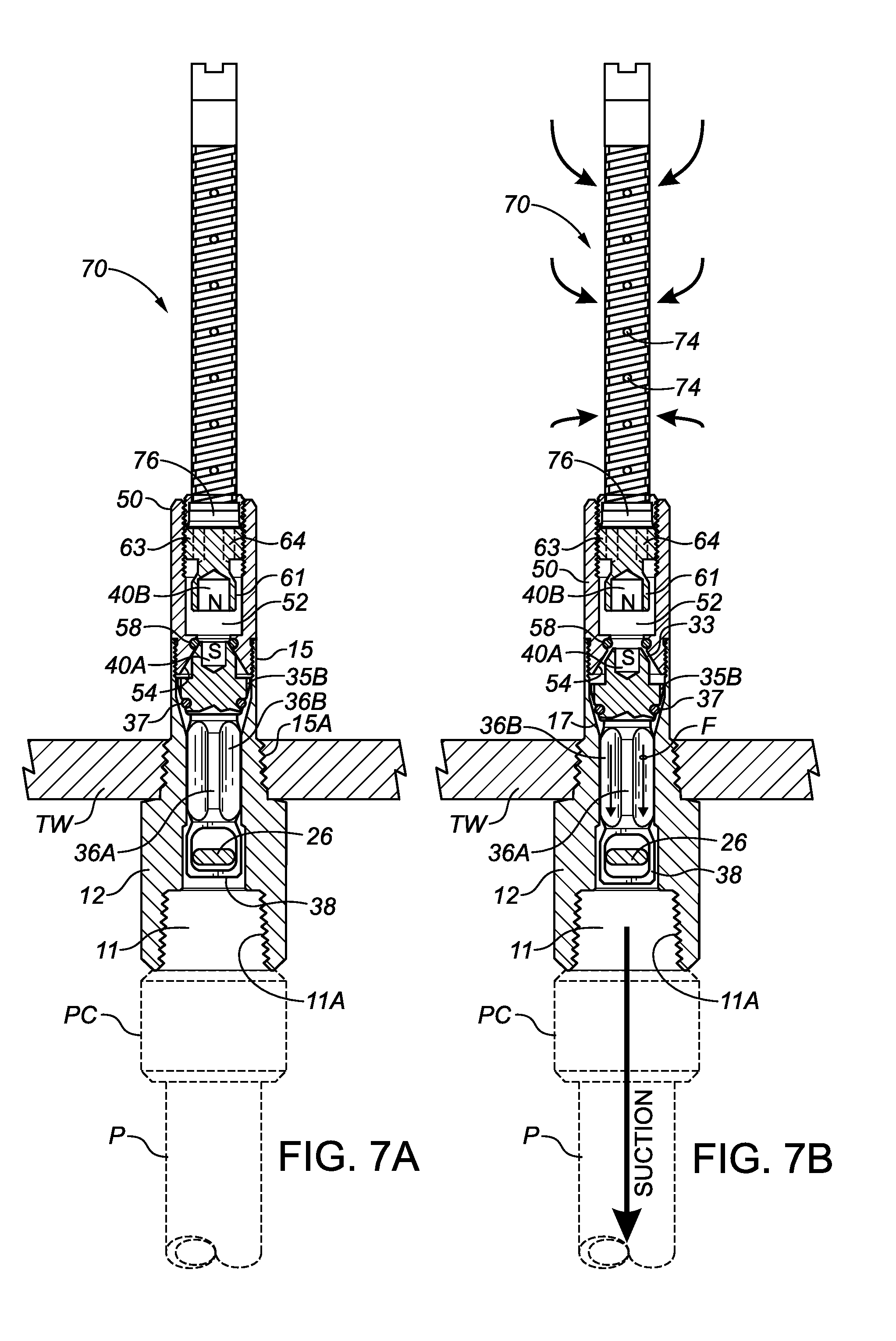
[0026]The accompanying Figures illustrate one non-limiting embodiment of a magnetic safety valve 100 in accordance with the present disclosure. Valve 100 includes a main valve body comprising an outer valve body 10 and an inner valve body 50. Outer valve body 10 has an outer section 12 and an inner section 15, with inner section 15 having an externally threaded section 15A for mounting valve 100 in an opening through the wall of a storage tank. A bore 11 extends through outer valve body 10, and an outer region of bore 11 is adapted (such as by internal threading 11A as illustrated) to facilitate connection to piping P leading to a pump or other appliance. A transverse bore 19 is provided through the wall of outer section 12 of outer valve body 10 for receiving a valve actuating assembly 20.

[0027]In the illustrated embodiment, valve actuating assembly 20 comprises an actuating handle 22 connected to a cylindrical shank 24 rotatably disposable within transverse bore 19, in conjunction...


PUM


Abstract

A magnetic safety valve for installation through a tank wall incorporates a piston movable within a valve body. The valve is held normally-closed by two opposite-pole magnets, one in the inner end of the piston, and one in the valve body. A vacuum produced by a pump connected to the valve will act upon the outer end of the piston, producing a force tending to move the piston outward. When the vacuum-induced outward force on the piston exceeds the attractive force between the two magnets, it pulls the piston outward and away from the valve body magnet, unseating the inner end of the piston from the valve body, and allowing outward fluid flow through the valve. A second valve seat may be provided for engagement with an outer portion of the piston to prevent uncontrolled fluid flow out of the tank in the event of valve damage.

Description

CROSS-REFERENCE TO RELATED APPLICATIONS[0001]This application claims the benefit, pursuant to 35 U.S.C. 119(e), of U.S. Patent Application No. 61 / 468,966, filed Mar. 29, 2011, and said earlier application is incorporated herein by reference in its entirety for continuity of disclosure.FIELD OF THE DISCLOSURE[0002]The present disclosure relates in general to valves for regulating flow from fluid storage tanks, and in particular to valves adapted to close in the event of significant physical damage.BACKGROUND[0003]A need exists for the prevention of uncontrolled flow of fluids from storage tanks to the environment as a result of piping breaches, equipment failures, or acts of vandalism. This is the case for tanks used to store many different types of fluids, including various chemicals, acids, and fuel oils, to name only a few. One common example is a storage tank containing fuel oil for an oil-fired furnace in an adjacent house or other building.[0004]To access the contents of such s...

Claims


Application Information

Patent Timeline
Patent Type & Authority Patents(United States)
IPC IPC(8): F16K31/08
CPCF16K24/06F16K31/084Y10T137/7897Y10T137/7904
Inventor HASELOH, PETER G.MANUEL, KIRSTE ANN
Owner HASELOH PETER G
Why Eureka
Try Eureka