Foldable sliding wall and carriage

a technology of sliding wall and sliding carriage, which is applied in the direction of door/window fittings, wing suspension devices, building components, etc., can solve the problems of known devices causing annoying noises, and achieve the effect of minimal effor

Active Publication Date: 2014-03-18
HAWA AG
View PDF21 Cites 23 Cited by
  • Summary
  • Abstract
  • Description
  • Claims
  • Application Information

AI Technical Summary

Benefits of technology

[0011]It shall be possible to operate the foldable sliding wall with only one motorised carriage, so that a minimum effort results for driving and controlling the foldable sliding wall.
[0012]It shall be p...

Problems solved by technology

Thereby annoying noises ...

Method used


Image

  • Foldable sliding wall and carriage
  • Foldable sliding wall and carriage
  • Foldable sliding wall and carriage

Examples


Embodiment Construction

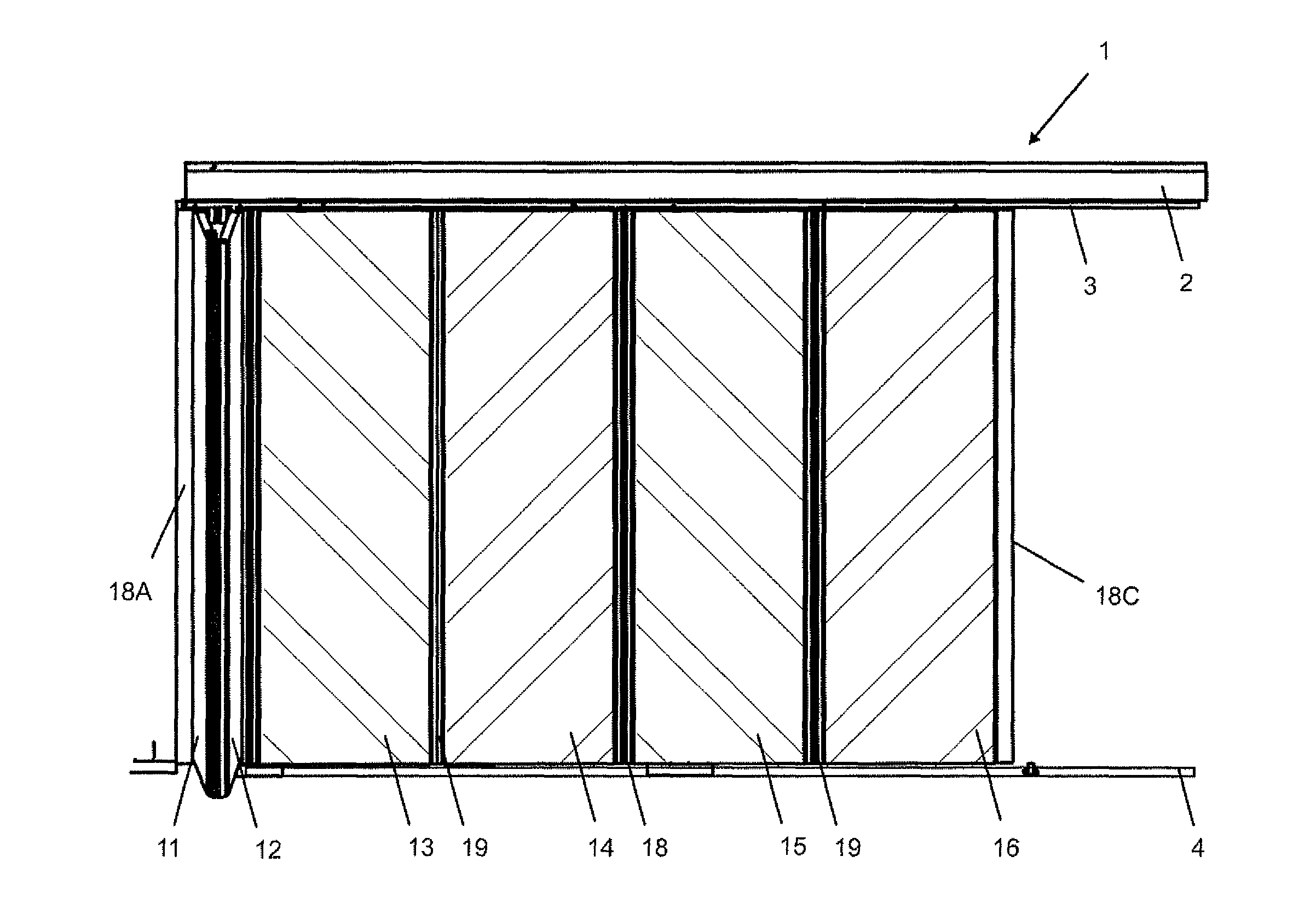
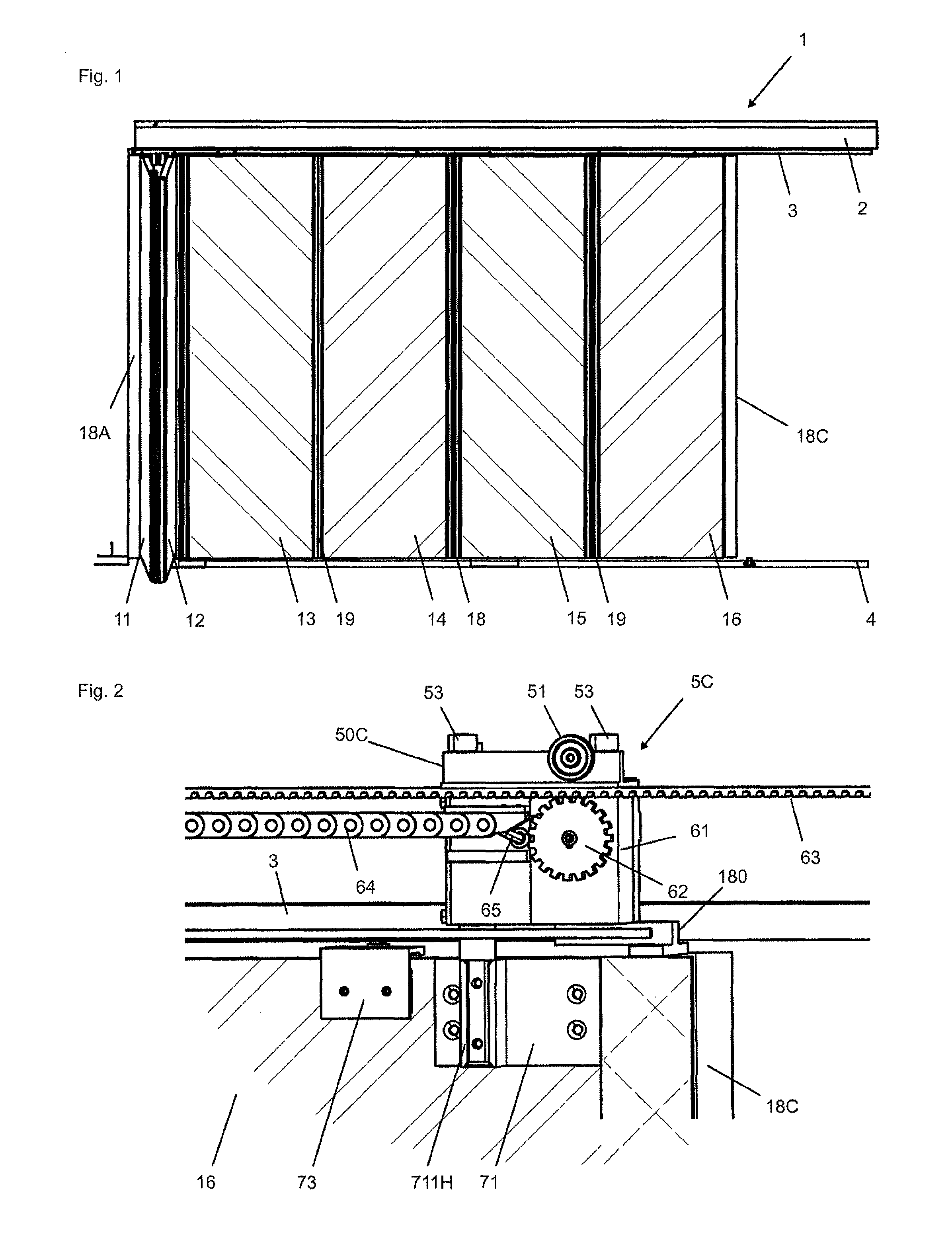
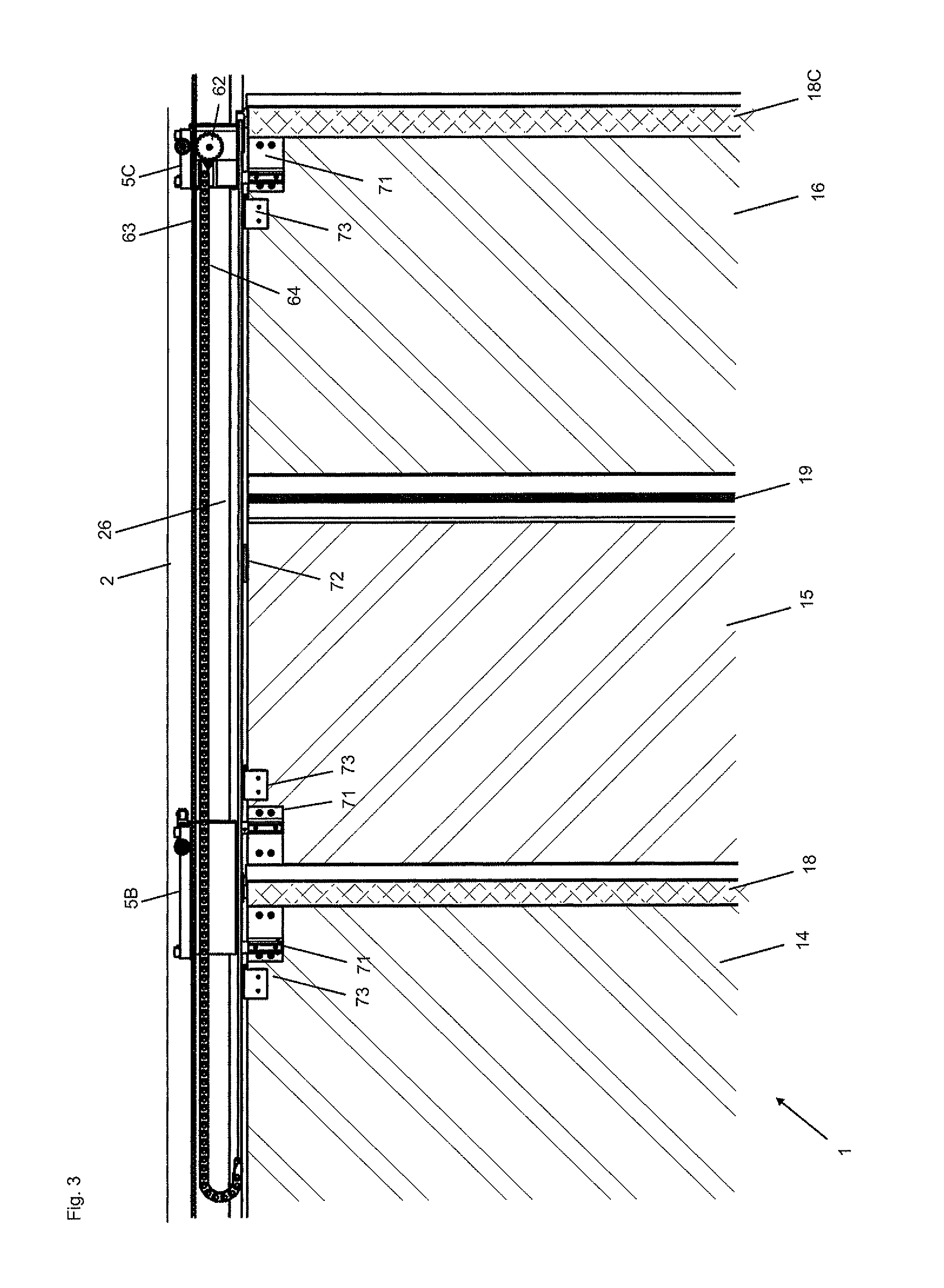
[0064]FIG. 1 shows an inventive foldable sliding wall 1 with six wall elements 11, 12, 13, 14, 15, 16, that are guided on the ceiling side with a head rail 2 and a stabilising rail and on the floor side with a foot rail 4. The wall elements 11, . . . , 16 form three wall pairs 11, 12; 13, 14; and 15, 16, between which protection profiles 18 are provided. The wall elements of each wall pair 11, 12; 13, 14; and 15, 16 are connected with one another on one end through a hinge 19 and on the other end held with carriages 5A, 5B, 5C (see FIGS. 3 and 4b), that are described below. At the front side and the end side of the foldable sliding wall 1 the corresponding wall elements 11 and 16 are provided each with a terminating profile 18A, 18C, which for example can be moved into a receiving profile.

[0065]FIG. 1 further shows that the first wall pair of wall elements 11, 12 is folded and perpendicularly aligned to the head rail 2. The process of folding the foldable sliding wall is executed se...


PUM


Abstract

The foldable sliding wall includes at least a first and a second wall element that are pivotally connected to one another and pivotally held by a first and a second head carriage, which are displaceably supported in a head rail. A first head fitting is mounted at the upper side of the first wall element and is connected to a first shaft, which is supported in a first carriage body of the first head carriage and a second head fitting is mounted at the upper side of the second wall element and is connected to a second shaft, which is supported in a second carriage body of the second head carriage.

Description

BACKGROUND OF THE INVENTION[0001]The invention relates to a foldable sliding and to a carriage for this foldable sliding wall.[0002]In order to separate or form rooms or room areas, for closing room openings or window openings and for covering fronts or facades often wall elements, such as sliding doors are used, which are mounted, possibly mounted so as to be rotatable, on carriages that are displaceable along a rail. Sliding doors of this kind are made for example from transparent glass, wood or metal. Often, the wall elements are coupled with one another, so that the combination of all elements forms a foldable sliding wall or a folding sliding shutter. Individual wall elements or a plurality of wall elements combined with one another are also used in furniture units, particularly in wardrobes.[0003]In [1], U.S. Pat. No. 6,397,522B1, a sliding-rotating leaf system is disclosed that serves for enclosing a balcony with glass and that comprises several sliding-rotating wall elements...

Claims


Application Information

Patent Timeline
IPC IPC(8): E04H1/00
CPCE05D15/58E04B2/7401E05F15/103E05D15/0652E05D15/0604E05Y2201/614E05F15/605E05Y2900/15E05Y2400/654E05Y2800/344
Inventor HAAB, GREGORETTMULLER, PETERWUTHRICH, HANSYEZZA, NEJIB
Owner HAWA AG
Why Eureka
Try Eureka