Lighting apparatus and circuits for lighting apparatus
a lighting apparatus and circuit technology, applied in the field of lighting, can solve the problems of not providing a full spectrum white light, not providing a high color rendering index, and not providing a full spectrum
- Summary
- Abstract
- Description
- Claims
- Application Information
AI Technical Summary
Benefits of technology
Problems solved by technology
Method used
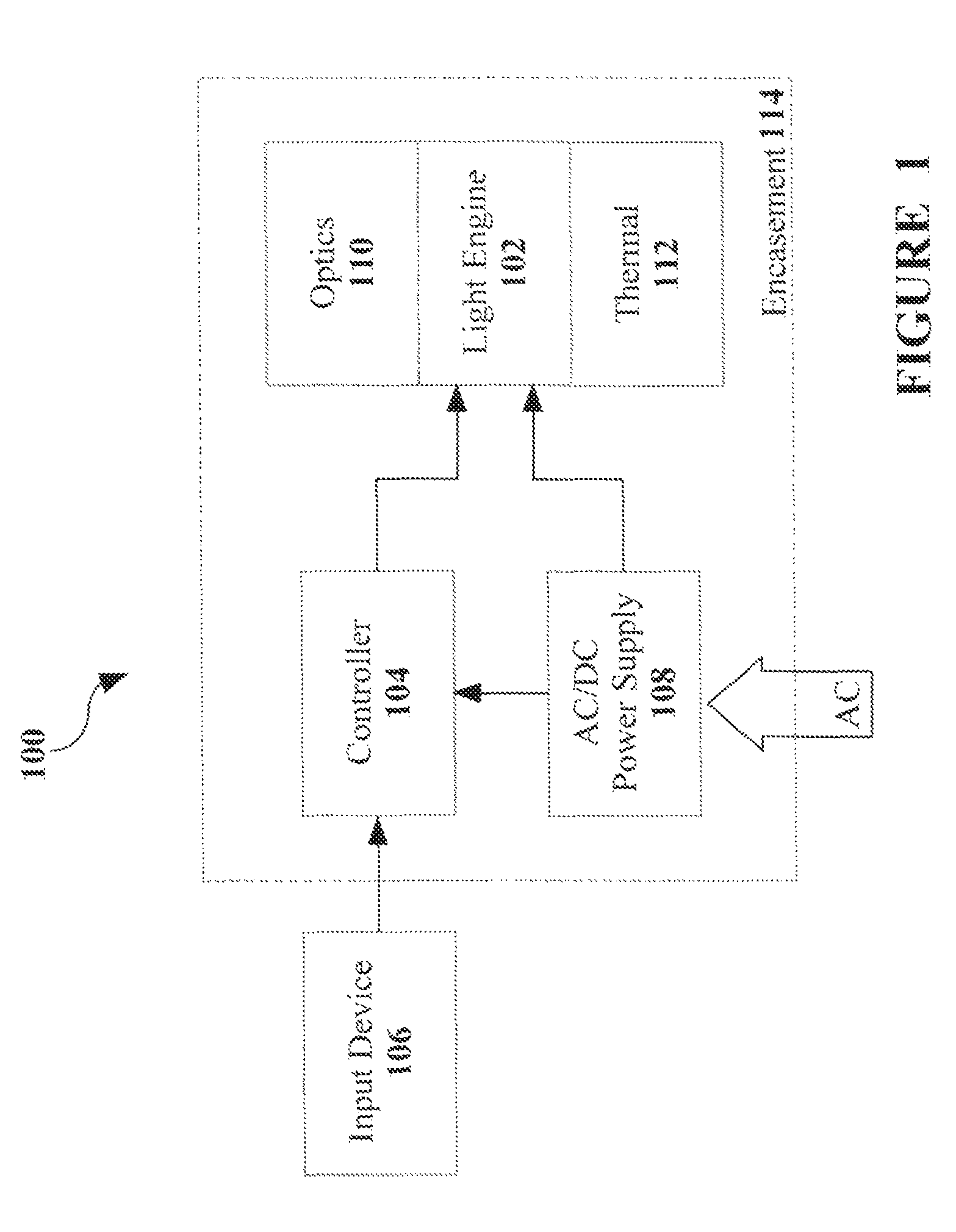
Image

Examples
first embodiment
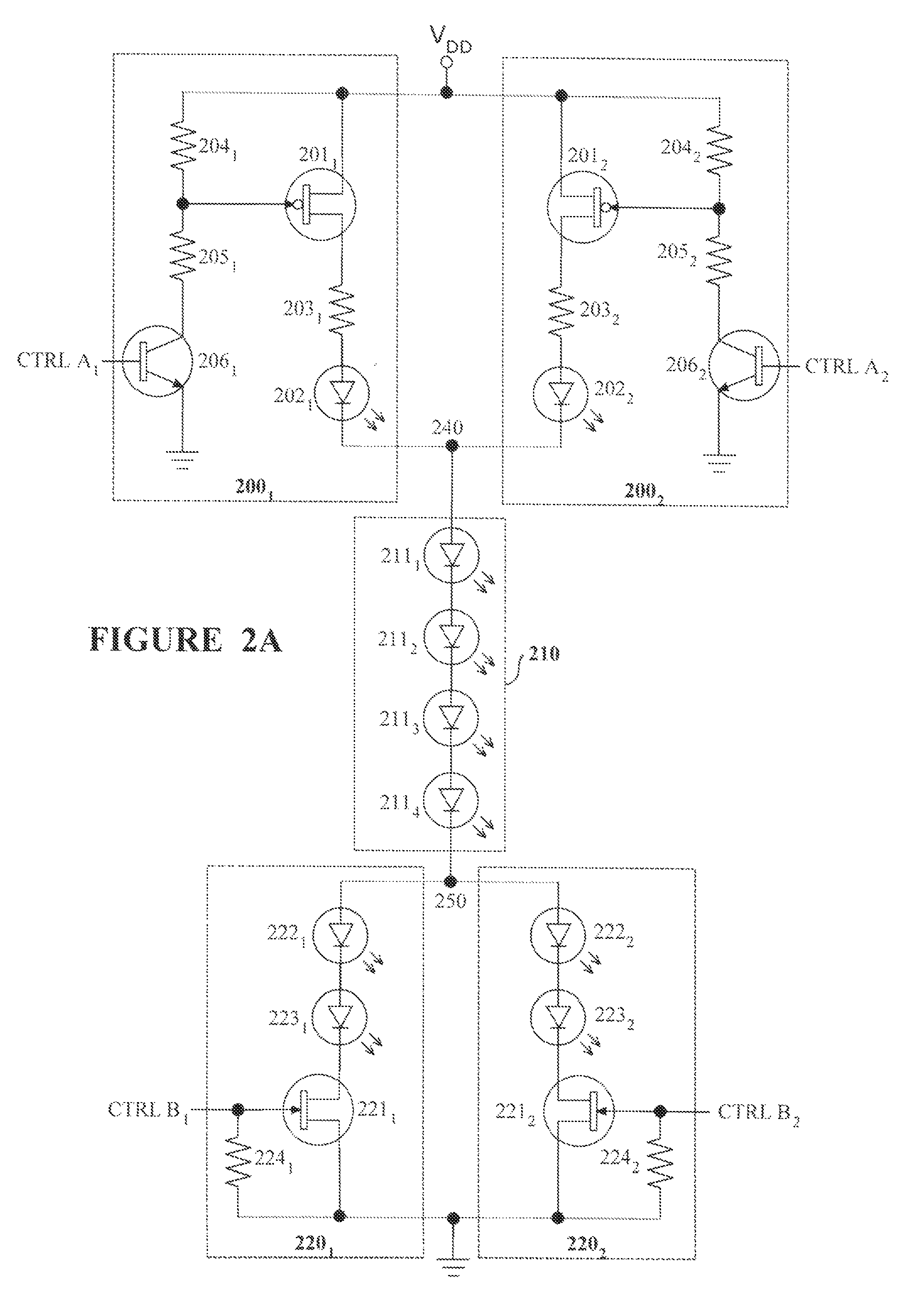
[0054]FIG. 2A is an electrical circuit diagram of a light engine according to the present invention. This embodiment is a specific example in which ten LEDs are used to create four potential output light spectrum boundary points by activating one of four potential current paths. In operation as will be described below, only seven of the LEDs are activated at any one time. Within FIG. 2A, the light engine 102 comprises first and second parallel circuits 2001,2002, coupled in parallel between a power rail (VDD) and a first common node 240; a common circuit 210 coupled between the first common node 240 and a second common node 250; and third and fourth parallel circuits 2201,2202 coupled in parallel between the second common node and a ground rail.
[0055]Each of the first and second parallel circuits 2001, 2002 comprises a corresponding p-channel switching transistor 2011,2012 coupled in series with a resistor 2031,2032 and an LED 2021,2022 respectively. The sources of the p-channel tra...
second embodiment
[0072]FIG. 2B is an electrical circuit diagram of a light engine according to the present invention. The light engine of FIG. 2B is a modified light engine to the light engine described above with reference to FIG. 2A. Within FIG. 2B, the fourth parallel circuit 2202 has been modified and further comprises an additional n-channel switching transistor 2213 and an additional second LED 2233. In this embodiment, the source of the additional n-channel transistor 2213 is coupled to the ground rail and the additional second LED 2233 is coupled between the drain of the additional n-channel transistor 2213 and a node 260 between the first LED 2222 and the second LED 2232. The fourth parallel circuit 2202 further comprises an additional pull-down resistor 2243 coupled between the gate of the additional n-channel transistor 2213 and the ground rail. The gate of the additional n-channel transistor 2211 is further coupled to a corresponding control signal CTRL B3.
[0073]In the circuit of FIG. 2B...
PUM
 Abstract
Description
Claims
Application Information
 - R&D
- Intellectual Property
- Life Sciences
- Materials
- Tech Scout
- Unparalleled Data Quality
- Higher Quality Content
- 60% Fewer Hallucinations
Browse by: Latest US Patents, China's latest patents, Technical Efficacy Thesaurus, Application Domain, Technology Topic, Popular Technical Reports.
© 2025 PatSnap. All rights reserved.Legal|Privacy policy|Modern Slavery Act Transparency Statement|Sitemap|About US| Contact US: help@patsnap.com