
Radome incorporating partition wall for enhancing isolation between transmitted and received radar waves of radar apparatus

a technology of radar apparatus and partition wall, which is applied in the direction of antenna details, instruments, antennas, etc., can solve the problems of reducing detection performance, difficult to achieve a sufficient degree of isolation between transmitted and received waves, and increasing reception noise, so as to increase manufacturing costs, enhance isolation, and increase the degree of isolation

Active Publication Date: 2014-03-18
DENSO CORP
View PDF15 Cites 5 Cited by
  • Summary
  • Abstract
  • Description
  • Claims
  • Application Information

AI Technical Summary

Benefits of technology

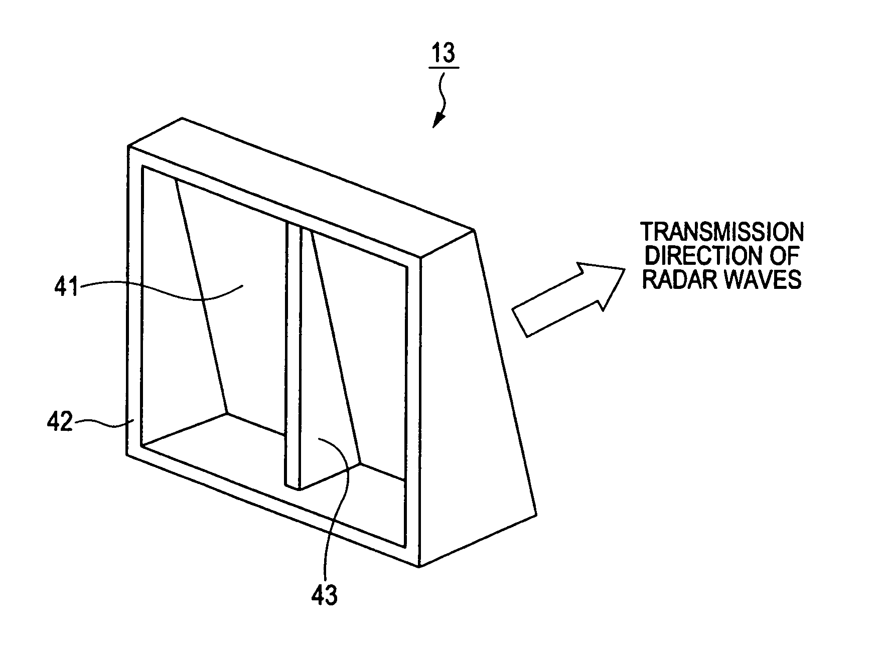
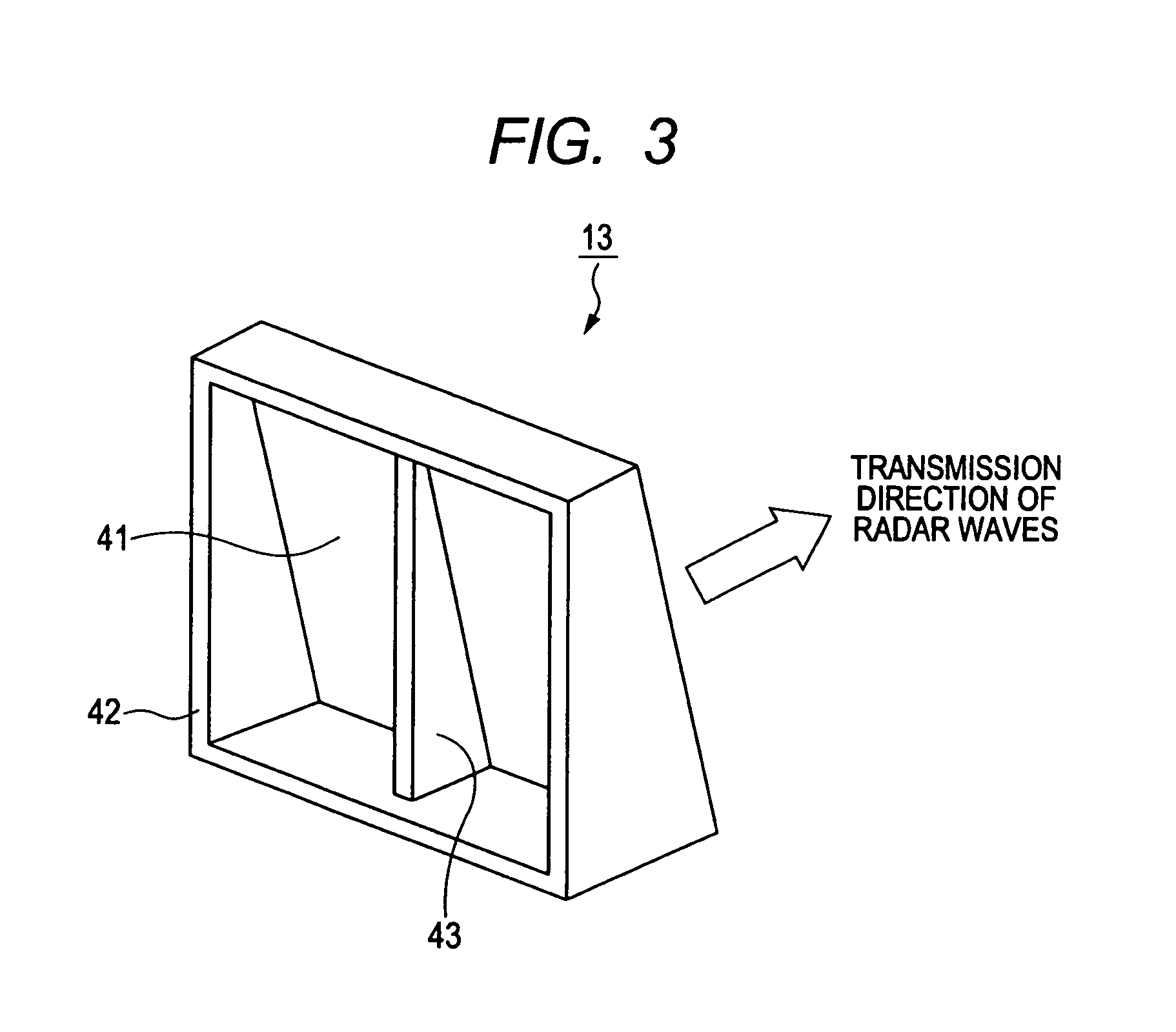
The present invention provides a radome made of a material transparent to radar waves for covering the antenna formation face of a millimeter-wave radar apparatus. This radome enhances isolation between transmitted and received waves without requiring additional component parts or manufacturing operations, and achieves a significantly increased degree of isolation between transmitted and received radar waves. The partition wall formed integrally with the radome reflects a significant proportion of the transmitted waves, and the greater the angle of incidence of the transmitted waves upon the partition wall, the greater the extent to which the incident waves are reflected. The invention enables the objective to be achieved without increasing manufacturing costs.

Problems solved by technology

However with such a configuration it is difficult to achieve a sufficient degree of isolation between transmitted and received waves.
Such directly received radar waves are indicated by the arrow lines in FIG. 4A, and produce increased reception noise.
This causes the noise floor of the received signal to be raised, thereby lowering the detection performance (e.g., reducing the maximum range at which target objects can be detected).
This raises the problem of increasing the number of component parts required for manufacturing the radar apparatus, and additional manufacturing operations for attaching the partition wall 160 to the antenna substrate 150.
Thus there is the disadvantage that the overall manufacturing cost of the radar apparatus becomes increased, due to incorporating the partition wall.

Method used


Image

  • Radome incorporating partition wall for enhancing isolation between transmitted and received radar waves of radar apparatus
  • Radome incorporating partition wall for enhancing isolation between transmitted and received radar waves of radar apparatus
  • Radome incorporating partition wall for enhancing isolation between transmitted and received radar waves of radar apparatus

Examples


Embodiment Construction

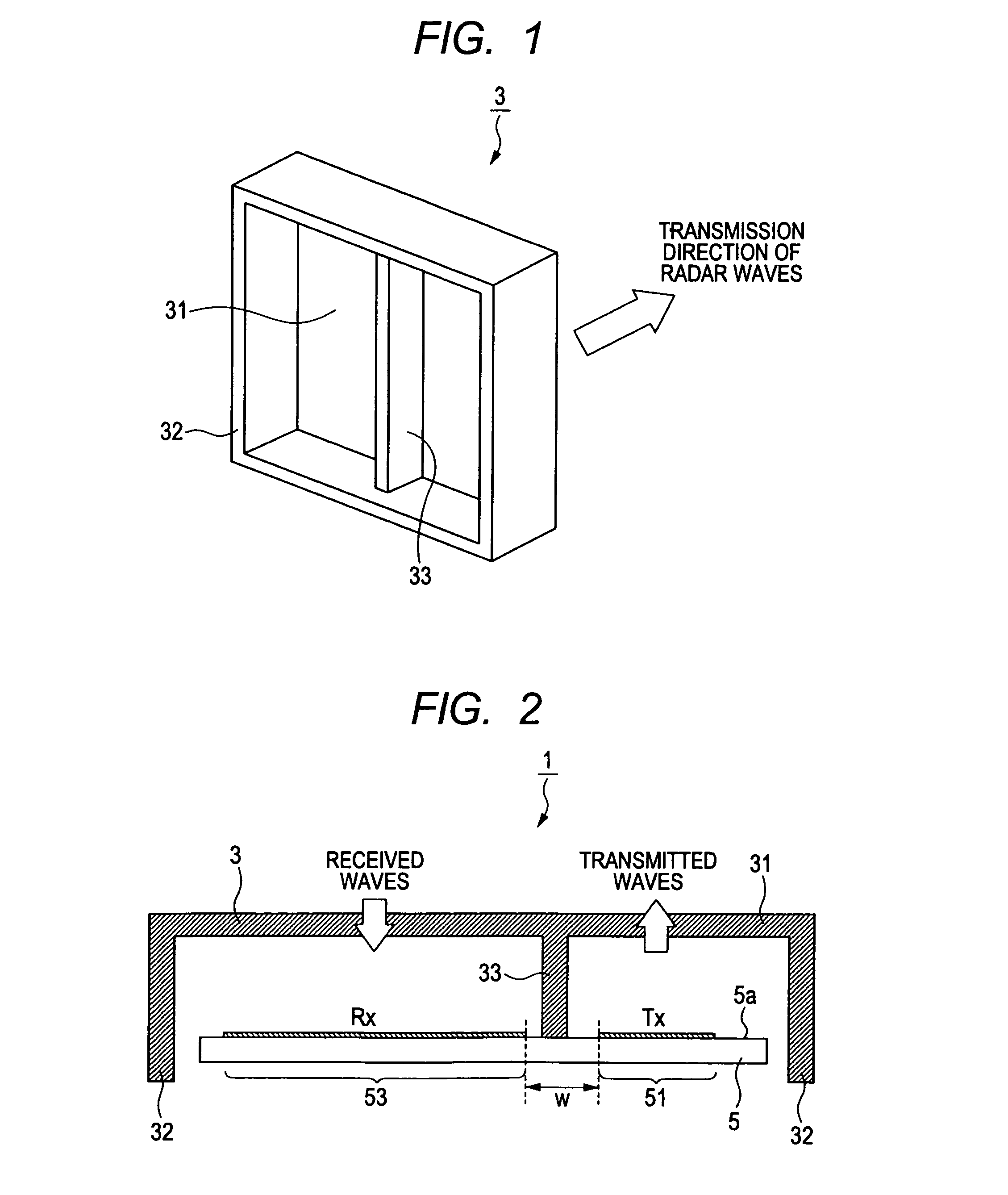
[0018]FIG. 1 is an oblique view showing the configuration of an embodiment of a radome, designated by numeral 3, while FIG. 2 is a cross-sectional view showing the radome 3 disposed covering an antenna substrate 5 of a radar apparatus 1, when installed in a radar apparatus 1. The antenna substrate 5 is part of a main body of the radar apparatus 1.

[0019]The radar apparatus 1 is designed for installation in a vehicle, for transmitting / receiving radar waves in the millimeter wavelength range (with this embodiment, 76.5 GHz radar waves). The radar apparatus 1 obtains information (range, velocity, position, bearing, etc.,) concerning target objects such as preceding vehicles, obstacles in the road, roadside objects, etc., based on received radar waves that are reflected from such target objects.

[0020]As shown in FIG. 1, the radome 3 is basically in the form of a rectangular box which is open on one side. In the following, the part of the radome 3 which forms the base of the internal spac...


PUM


Abstract

A radome covers an antenna substrate of a millimeter-band radar apparatus, with a partition wall formed integrally in the radome separating the internal space of the radome into a first internal space, located in correspondence with a transmitting antenna section, and a second internal space, located in correspondence with a receiving antenna section. Increased isolation between transmission and reception is achieved thereby, by reducing the amount of transmitted radar waves which directly reach the receiving antenna section.

Description

CROSS-REFERENCE TO RELATED APPLICATIONS[0001]This application is based on and incorporates herein by reference Japanese Patent Application No. 2010-242449 filed on 28 Oct. 2010.BACKGROUND OF THE INVENTION[0002]1. Field of Application[0003]The present invention relates to a radome incorporating a partition wall for providing enhanced isolation between transmitted and received radar waves, and to a radar apparatus incorporating the radome.[0004]2. Description of Related Art[0005]Types of radar apparatus are known, in particular for installation in a vehicle for detecting target objects ahead of the vehicle, which transmit / receive radar waves in the millimeter-wavelength range. Such a radar apparatus typically employs a planar antenna structure, in which a transmission section is formed of a pattern of conductive material formed on a planar face of substrate and a receiving section is similarly formed of a pattern formed on a substrate. An example of this is illustrated in the cross-se...

Claims


Application Information

Patent Timeline
Patent Type & Authority Patents(United States)
IPC IPC(8): H01Q1/42
CPCG01S2007/027G01S7/032G01S7/038H01Q1/525H01Q1/42G01S7/027
Inventor ANDO, TAKAMASANATSUME, KAZUMA
Owner DENSO CORP
Learn More