
Dual-polarized dual-feeding planar antenna

a planar antenna and dual-polarized technology, applied in the direction of antennas, resonant antennas, radiating element structural forms, etc., can solve the problem of limiting the application of antennas, and achieve the effects of reducing electromagnetic interference, enhancing isolation between two feeding ports, and increasing isolation

Inactive Publication Date: 2013-08-27
NAT CENT UNIV
View PDF5 Cites 8 Cited by
  • Summary
  • Abstract
  • Description
  • Claims
  • Application Information

AI Technical Summary

Benefits of technology

[0011]In view of the foregoing subject, an objective of the present invention is to provide a dual-polarized dual-feeding planar antenna that can increase the utility variety.
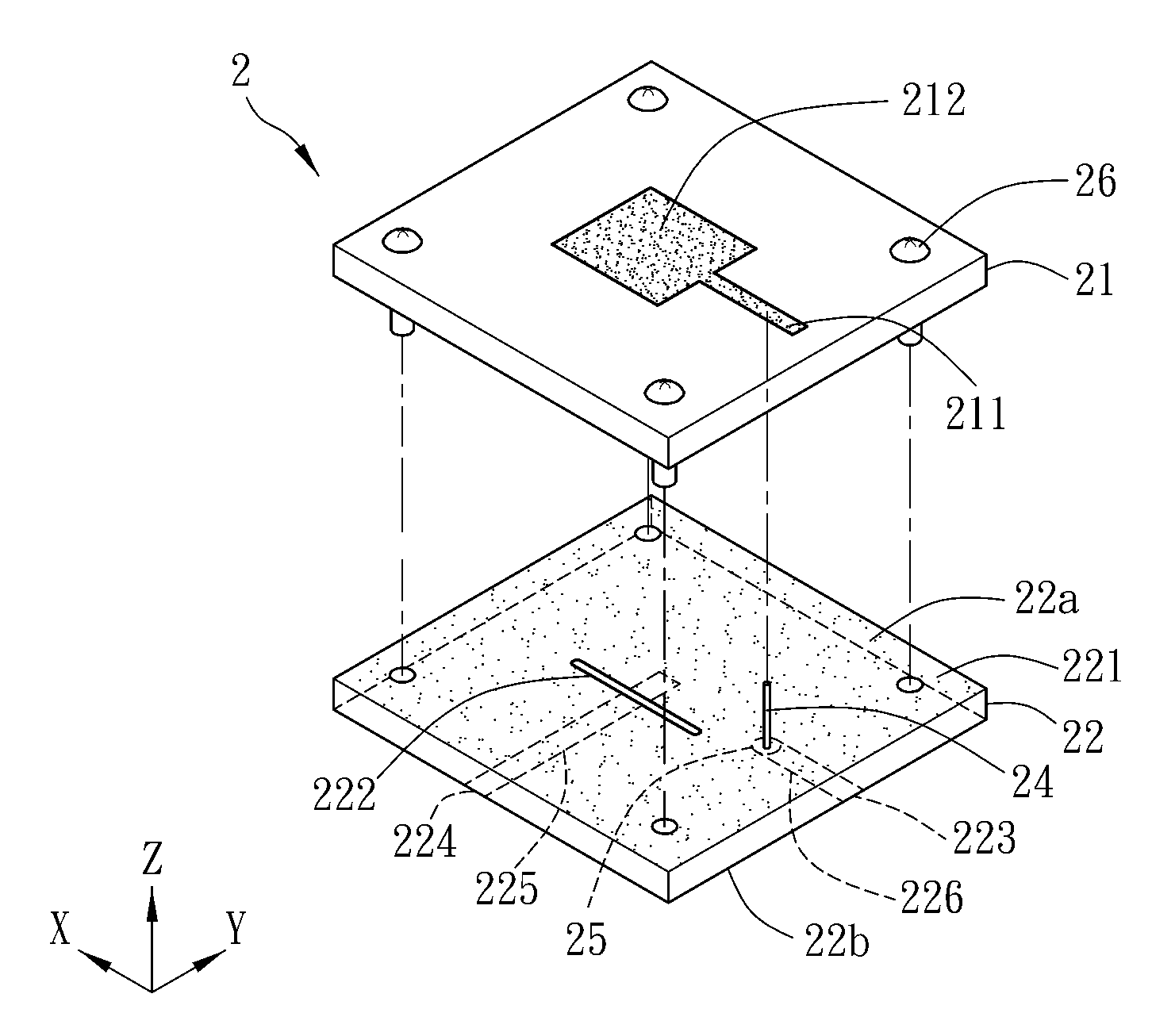
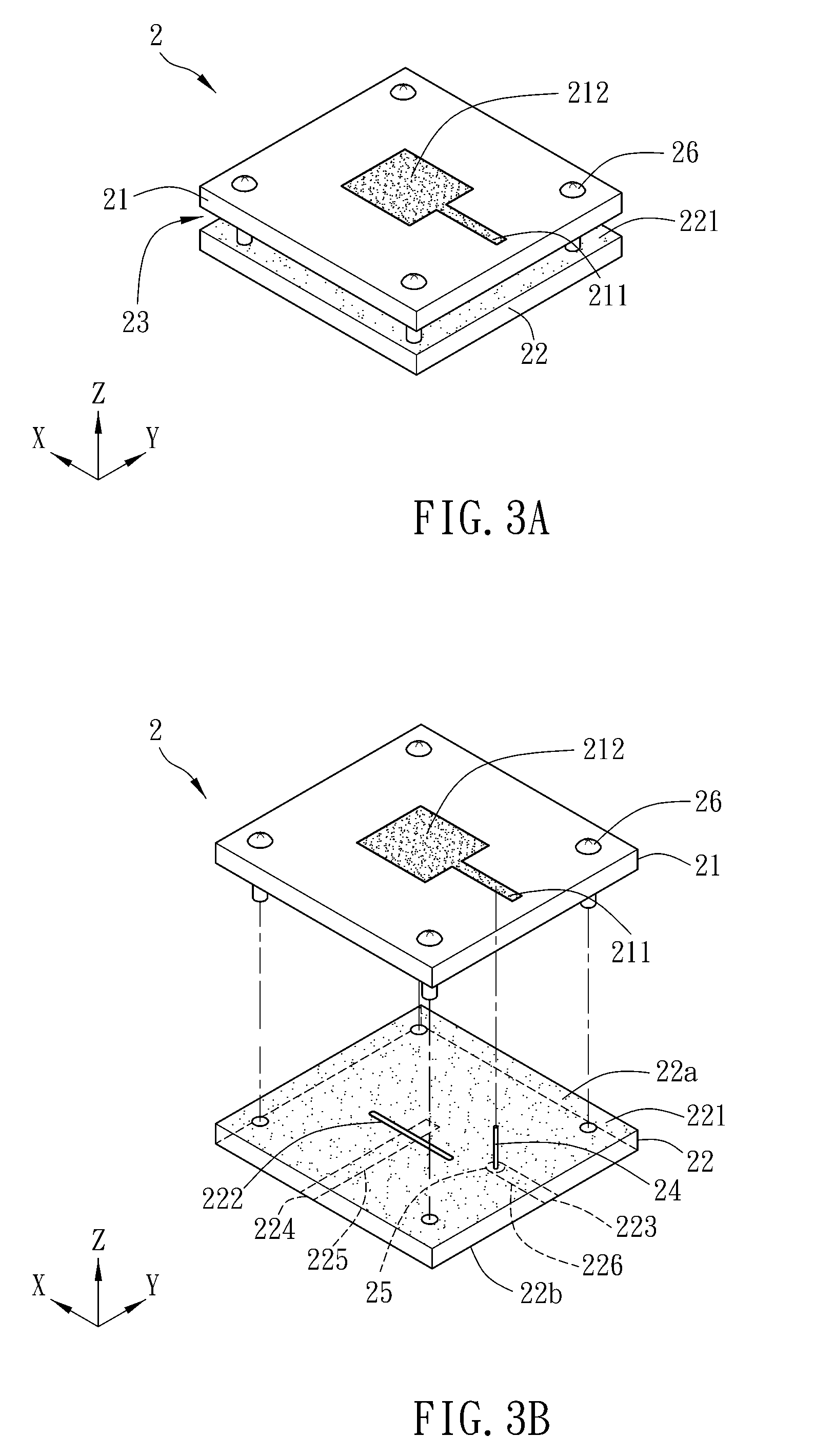
[0023]As mentioned above, the dual-polarized dual-feeding planar antenna of the present invention has an air layer disposed between two substrates, so that it is more flexible in various design purposes such as for bandwidths, beamwidths or impedance matching. In this invention, the first microstrip and the conductive wire are electrically connected to the first feeding port so as to provide a first polarization direction. In addition, the patch couples to the second microstrip via the slot and the second microstrip is electrically connected to the second feeding port, so that the energy of the patch can be coupled to the second microstrip through the slot and the second feeding port so as to provide a second polarization direction. Moreover, the common ground layer can separate two feeding ports, so the isolation between two feeding ports can be enhanced. In practice, the increased isolation can decrease the electromagnetic interference between the antenna and the post circuits. Compared with the prior art, the present invention can utilize the dual-feeding design to induce two polarization directions so as to increasing the utility variety.

Problems solved by technology

This limits the applications of the antenna.

Method used


Image

  • Dual-polarized dual-feeding planar antenna
  • Dual-polarized dual-feeding planar antenna
  • Dual-polarized dual-feeding planar antenna

Examples


first embodiment

[0036]FIG. 3A is a schematic diagram showing a dual-polarized dual-feeding planar antenna 2 according to the present invention, and FIG. 3B is an exploded view of the dual-polarized dual-feeding planar antenna 2. Referring to FIGS. 3A and 3B, the dual-polarized dual-feeding planar antenna 2 includes a first substrate 21, a second substrate 22 and an air layer 23.

[0037]The first substrate 21 includes a first microstrip 211 and a patch 212 electrically connected with each other. The shape of the patch 212 can be circular, elliptic, or rectangular. In this embodiment, the first substrate 21 is a printed circuit board and includes only one patch 212, and the patch 212 is, for example, a rectangular patch, which is formed on the surface of the first substrate 21 by the circuit printing process. In addition, the first microstrip 211 and the patch 212 can be located on the same surface or different surfaces of the first substrate 21. In this embodiment, the first microstrip 211 and the pat...

second embodiment

[0043]FIG. 4 is an exploded view of a dual-polarized dual-feeding planar antenna 2a according to the present invention. Referring to FIG. 4, the dual-polarized dual-feeding planar antenna 2a further includes a phase shift circuit 27, which is electrically connected with the first and second feeding ports 223 and 224. In this embodiment, the phase shift circuit 27 is, for example, a branch line coupler, and the feeding port 27b of the phase shift circuit 27 usually connects to a 50Ω load. Since the electrical length of each of the sections 271 and 272 of the coupler is about a quarter of the wavelength of the operation bandwidth, the phase difference between the first and second feeding ports 223 and 224 is 90 degrees as the energy is fed into the feeding port 27a. This can obtain a circular polarization antenna, which is capable of achieving right or left circular polarization.

third embodiment

[0044]FIG. 5A is a schematic diagram showing a dual-polarized dual-feeding planar antenna 3 according to the present invention, and FIG. 5B is an exploded view thereof. The antenna array composed of a plurality of patches is provided to reach the desired gain.

[0045]In this embodiment, the dual-polarized dual-feeding planar antenna 3 is a 2×2 array for example. Besides, the first substrate 31 of the dual-polarized dual-feeding planar antenna 3 further includes an impedance converter 318, which is electrically connected to the first microstrip 311. In addition, the second substrate 32 also includes an impedance converter 328, which is electrically connected to the second microstrip 325. Herein, the impedance converters 318 and 328 are used for impedance matching. The impedance converter 318 is a taper quarter-wavelength impedance converter, which can reduce the discontinuous effect during impedance converting.

[0046]In this embodiment, the planar antenna 3 also includes, for example, f...


PUM


Abstract

A dual-polarized dual-feeding planar antenna includes a first substrate, a second substrate and an air layer. The first substrate includes at least one first microstrip and at least one patch electrically connected with each other. The second substrate is disposed on one side of the first substrate and includes a common ground layer, a slot, a first feeding port, a second feeding port and a second microstrip. The slot is disposed corresponding to the patch. The air layer is disposed between the first substrate and the second substrate. The first microstrip is electrically connected to the first feeding port through a conducting wire. The patch couples to the second microstrip via the slot, and the second microstrip is electrically connected to the second feeding port.

Description

CROSS REFERENCE TO RELATED APPLICATIONS[0001]This Non-provisional application claims priority under 35 U.S.C. §119(a) on Patent Application No(s). 099139594 filed in Taiwan, Republic of China on Nov. 17, 2010, the entire contents of which are hereby incorporated by reference.BACKGROUND OF THE INVENTION[0002]1. Field of Invention[0003]The present invention relates to an antenna and, in particular, to a planar antenna.[0004]2. Related Art[0005]In the recent years, the satellite communication, especially for the live shows and TV programs, is rapidly developed, and thus more than ten commercial satellites are launched every year. In additional, the satellite TV channels increase and billion users are watching these channels. Accordingly, it is very important to develop a satellite signal receiving system that can provide good quality and function. In general, the satellite signal receiving antenna is commonly designed as a dish antenna, and the LNB feed thereof usually adopts the conve...

Claims


Application Information

Patent Timeline
Patent Type & Authority Patents(United States)
IPC IPC(8): H01Q1/38
CPCH01Q9/0435H01Q21/065H01Q21/0075
Inventor CHEN, TAI-LEE
Owner NAT CENT UNIV
Learn More