
Color LiDAR scanner

a lidar scanner and color technology, applied in the field of laser imaging detection and ranging systems, can solve problems such as system deficiency in one respect or another

Active Publication Date: 2014-03-18
VELODYNE LIDAR USA INC
View PDF15 Cites 250 Cited by
  • Summary
  • Abstract
  • Description
  • Claims
  • Application Information

AI Technical Summary

Problems solved by technology

Some have tried to produce color versions of LiDAR imaging systems, but such systems are deficient in one respect or another.

Method used


Image

  • Color LiDAR scanner
  • Color LiDAR scanner
  • Color LiDAR scanner

Examples


Embodiment Construction

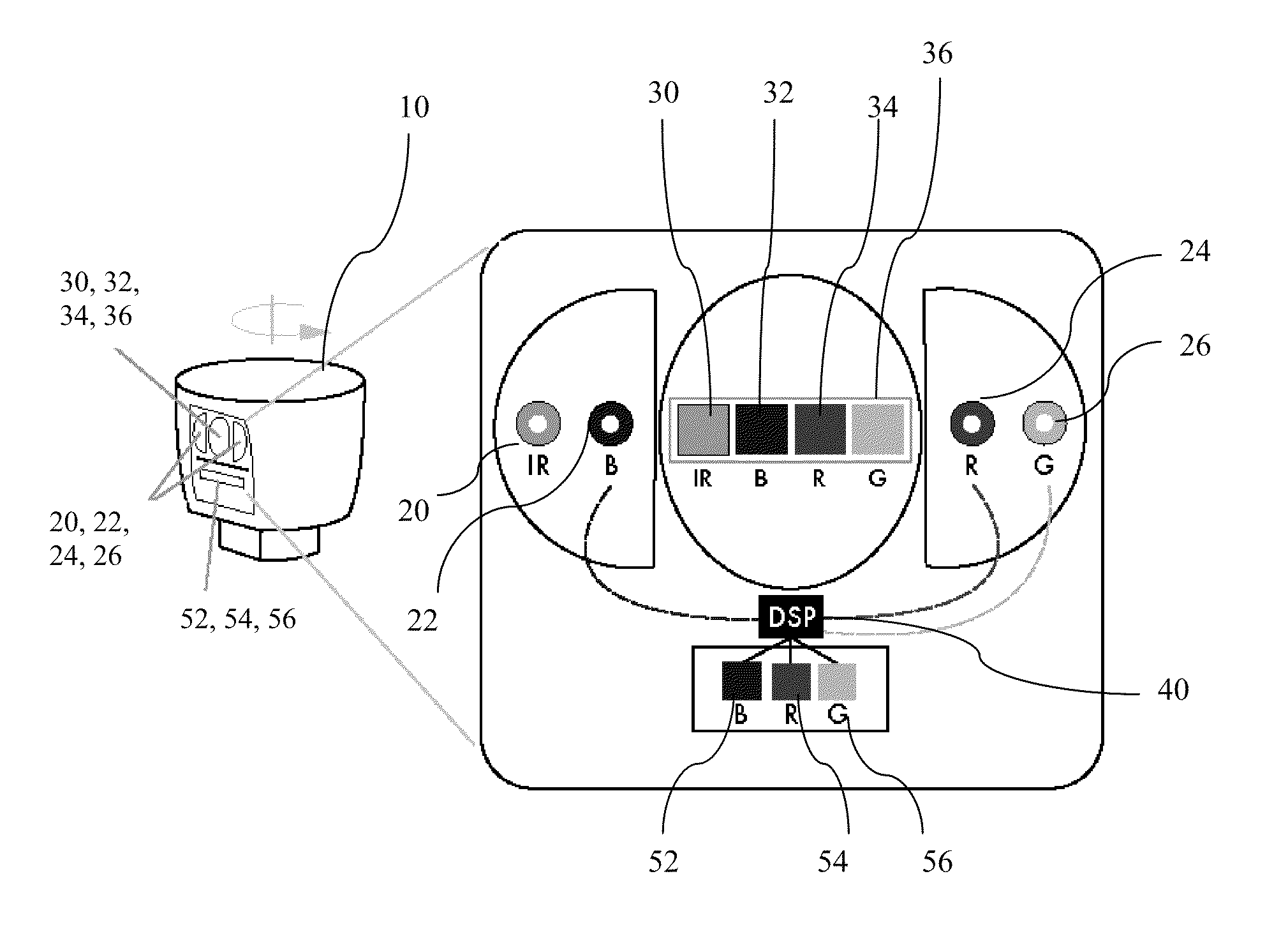
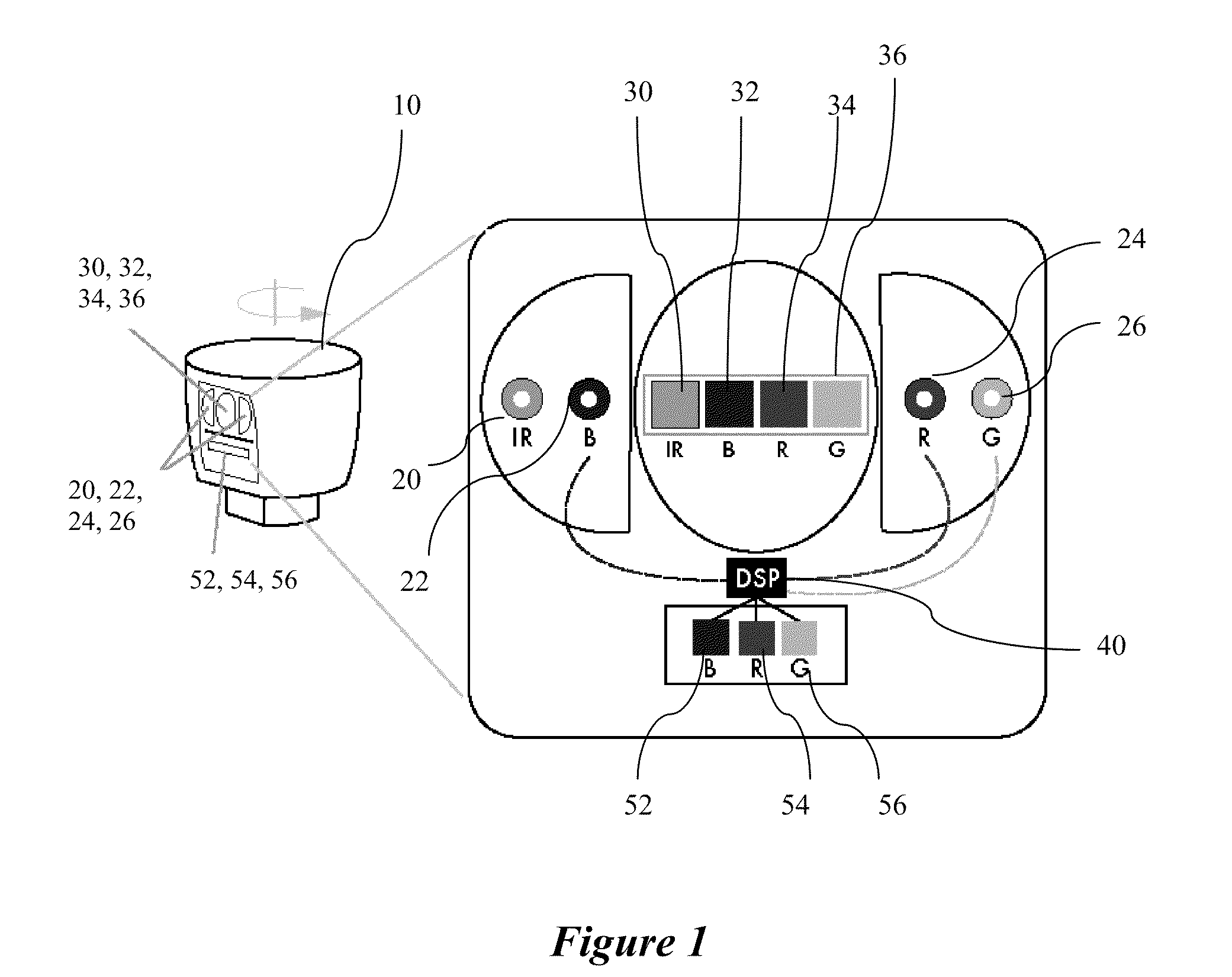
[0015]As shown in FIG. 1, a preferred version of a LiDAR scanning device is contained within a housing 10. The device in the illustrated version uses four laser diode emitters mounted to be able to send signals at a face of the housing: one each for infrared 20, blue 22, red 24, and green 26. Each emitter is fixed-aligned with a corresponding Avalanche Photodiode (APD) detector, 30, 32, 34, and 36 positioned to receive signals returned to the face of the housing. As shown, the four emitter / detector pairs (20-26 and 30-36) are aligned in a horizontal row that is generally perpendicular to a vertical axis extending through the housing. In a preferred version of the invention, one or more lenses is mounted in front of the emitter / detectors in order to focus the outgoing laser light and the returned light.

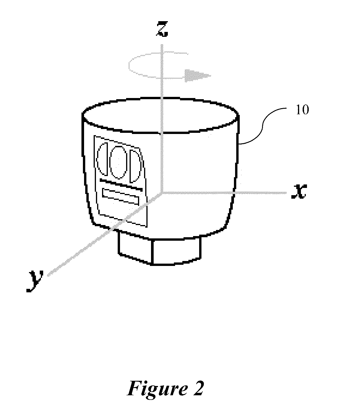
[0016]The housing 10 is positioned and configured so that it can be driven by a motor (not shown) to rotate about the vertical axis that is perpendicular to the horizontal row formed b...


PUM


Abstract

A color LiDAR scanner device includes color laser diodes (red, green, blue) and avalanche photodetector diodes (red, green, blue) that illuminate and detect the color light intensity returned from a target. In a preferred version these color laser / detectors are coupled with a single infrared laser / detector that detects the range and infrared light intensity from the same target. The combined range and color intensity information is combined to produce a single colored pixel in space. Multiple illuminations are used to create multiple pixels which can be combined to produce images. A rotating housing may be used for an entire surrounding image.

Description

PRIORITY CLAIM[0001]This application claims the benefit of prior provisional application Ser. No. 61 / 183,265 filed on Jun. 2, 2009, the contents of which are hereby incorporated by reference.FIELD OF THE INVENTION[0002]This invention relates generally to systems and methods for laser imaging detection and ranging, particularly including such systems that are capable of processing both ranging and color information.BACKGROUND OF THE INVENTION[0003]There are many laser imaging detection and ranging (LiDAR) range-finding systems that can capture a pixilated image in 2D and 3D format. These sensors use Infrared (IR) lasers to issue a pulse of light that travels to a target that then bounces off and returns to a detector. By tracking the time of flight of the light pulse, a distance can be calculated. This distance, combined with the position and directional angle of the sensing device, can be converted to a pixel in 3D space. Multiple pixels are combined to form images, including three-...

Claims


Application Information

Patent Timeline
Patent Type & Authority Patents(United States)
IPC IPC(8): G01C3/08
CPCG01C3/08G01S17/87G01C1/04G01S17/89G01S7/4815G01S7/4817
Inventor HALL, DAVID, S.
Owner VELODYNE LIDAR USA INC
Learn More