Monocular three-dimensional imaging

a three-dimensional imaging and monocular technology, applied in the field of imaging, can solve the problems of object displacement, high cost of multiple camera/lens system, and high computational cost of processing large target feature disparities between one sensor and another,

Active Publication Date: 2014-03-18
MEDIT CORP
View PDF70 Cites 10 Cited by
  • Summary
  • Abstract
  • Description
  • Claims
  • Application Information

AI Technical Summary

Benefits of technology

The patent describes a three-dimensional imaging system that uses a single primary optical lens and various configurations of apertures to capture optical channels. The system includes a sampling facility that redirects the optical channels to optical sensors, and an image processing facility that processes the data captured by the sensors. The system can be used in a camera or other imaging devices. The technical effects of the invention include improved depth of field, reduced aberration, and improved image quality.

Problems solved by technology

However, in machine vision systems this approach has shortcomings, such as the high cost of multiple camera / lens systems and the high computational cost of processing large target feature disparities between one sensor and another.
However, unlike stereo systems, the object is displaced in both the horizontal and vertical directions among the three cameras.

Method used


Image

  • Monocular three-dimensional imaging
  • Monocular three-dimensional imaging
  • Monocular three-dimensional imaging

Examples


Embodiment Construction

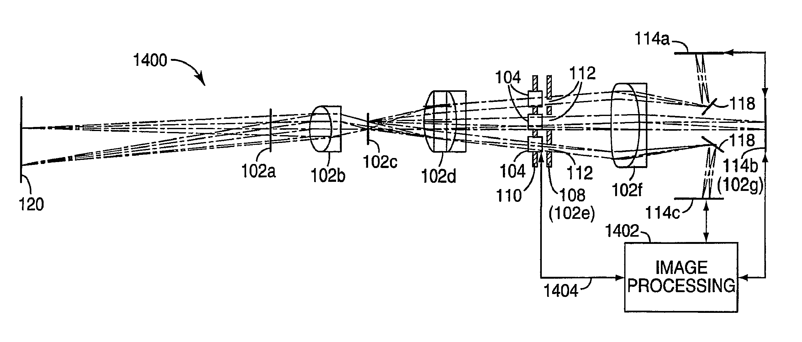
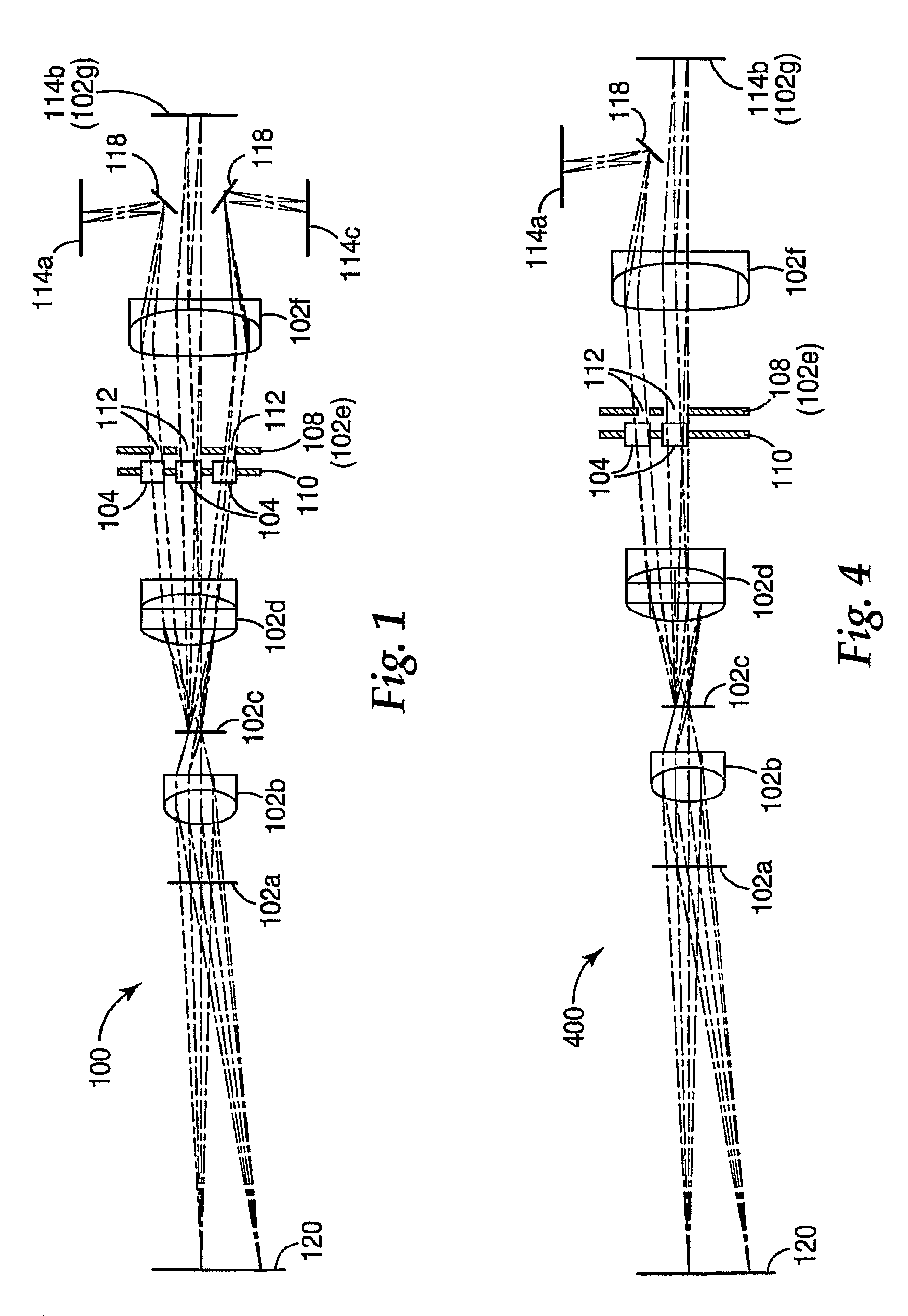
[0070]It will be understood that the ray traces and lenses depicted in the following figures are for purposes of illustration only, and depict optical paths generally in the disclosed systems. The ray traces and lens shapes should not be understood to limit the scope of the invention in any sense including the magnitude, direction, or focus of light rays or bundles passing through various optical components, notwithstanding any variations in number, direction, shape, position or size thereof, except as expressly indicated in the following detailed description.

[0071]Referring to FIG. 1, a schematic diagram of an imaging system 100 in accordance with one preferred embodiment of the present disclosure is depicted, including various optional components. The imaging system 100 may include a primary optical facility 102, which may be employed in any kind of image processing system. In general, a primary optical facility refers herein to an optical system having one optical channel. Typica...


PUM


Abstract

A three-dimensional imaging system uses a single primary optical lens along with various configurations of apertures, refocusing facilities, and the like to obtain three offset optical channels each of which can be separately captured with an optical sensor.

Description

CROSS REFERENCE TO RELATED APPLICATIONS[0001]This application is a national stage filing under 35 U.S.C. 371 of PCT / US2007 / 003947,filed Feb. 13, 2007, which claims benefit of U.S. Provisional Application No. 60 / 773,132, filed Feb. 13, 2006, and which is a continuation of applications: U.S. application Ser. No. 11 / 530,413 filed Sep. 8, 2006, U.S. application Ser. No. 11 / 530,420 filed Sep. 8, 2006, and U.S. application Ser. No. 11 / 530,428 filed Sep. 8, 2006 which is now Issued U.S. Pat. No. 7,372,642 the disclosure of which is incorporated by reference in their entirety herein.BACKGROUND[0002]1. Field of the Invention[0003]This invention relates to the field of imaging, and more particularly to the field of pupil sampling for multi-view three-dimensional imaging.[0004]2. Description of the Related Art[0005]One approach to capturing three-dimensional depth information is the use of a pair of two-dimensional recording devices whose relative orientation is known. Much like human or anima...

Claims


Application Information

Patent Timeline
Patent Type & Authority Patents(United States)
IPC IPC(8): H04N13/00H04N13/02
CPCG02B5/005G03B35/10H04N13/0282H04N13/0242G02B27/106G02B27/22H04N13/0217G03B35/08H04N13/218H04N13/243H04N13/282
Inventor ROHALY, JANOSHART, DOUGLAS P.
Owner MEDIT CORP
Why Eureka
Try Eureka