Thermal management of a propulsion circuit in an electromagnetic munition launcher

a propulsion circuit and electromagnetic technology, applied in the direction of launching weapons, white arms/cold weapons, weapons, etc., can solve the problems of incompatibility of delay and rapid-fire needs, and achieve the effect of less charge, less time, and more energy-efficien

Inactive Publication Date: 2014-03-25
LOCKHEED MARTIN CORP
View PDF30 Cites 9 Cited by
  • Summary
  • Abstract
  • Description
  • Claims
  • Application Information

AI Technical Summary

Benefits of technology

[0024]It should be noted that the thermal management provided by the recovery state need not be exclusive to the launcher, because in some embodiments, additional thermal management techniques supplement the recovery state, for example, but not limited to, forced air cooling, liquid cooling, improved materials, improved components, etc., depending upon the operational requirements of the launcher (e.g., the firing rate). Thus, in some embodiments, the thermal management provided by the recovery state has the capacity to reduce or eliminate supplemental techniques that would be otherwise employed, resulting in the advantageous effects recited above—namely lower weight, lower volume, and / or lower costs associated with deploying and maintaining the launcher.
[0025]The “charging state” charges the high-energy capacitor from a prime power source to prepare the propulsion circuit for the next launch. A charging state that follows the recovery state delivers less charge to the high-energy capacitor, because the recovery state partially recharged it. Consequently, the charging state takes less time when it follows the recovery state as compared to charging after launching, i.e., as compared to prior art designs. Moreover, the launcher is more energy-efficient. The inventors experimentally demonstrated that as much as 20 percent of the power needed to fully charge the high-energy capacitor was recovered through the recovery state.
[0026]The “safe state” provides a way to discharge energy present in the propulsion circuit via a load component(s). The safe state is triggered in case of a misfire or for another purpose that requires a safe discharge of energy away from the propulsion coil. The safe state discharges the high-energy capacitor via the load component. In contrast to the recovery state, the safe state relies on heat dissipation in the load component(s) to discharge excess energy. In some embodiments the safe state operates in conjunction with the recovery state.
[0027]The enhanced propulsion circuit according to the present invention comprises a plurality of switches. The switches are arranged and electrically coupled such that, depending on the open and closed positions of the respective switches, they actuate one of the disclosed states. By rapidly changing the configuration of the switches at the right time, i.e., actuating the recovery state following a launch (drive state), the significant residual propulsion coil energy is captured and stored for the next launch. Minimizing the energy loss has a major impact on operational efficiency, reduced heating of the propulsion coils, coil lifetimes, launcher repetition rate, and the total number of launcher shots per burst.
[0028]An apparatus according to the present invention is a propulsion circuit in an electromagnetic munition launcher that is capable of launching a munition, the propulsion circuit comprising: a first coil that is dimensioned and arranged to inductively couple to a second coil in an armature circuit that is associated with the munition; a high-energy capacitor; a diode having an anode that is dimensioned and arranged to electrically couple to the high-energy capacitor and having a cathode that is dimensioned and arranged to electrically couple to a first terminal of the first coil; and a plurality of switches for actuating a plurality of states of the propulsion circuit, the plurality of states comprising: a drive state that is actuated when a first switch is in a closed position and a second switch is in the closed position, wherein the high-energy capacitor discharges and a first flow of electric current through the first coil inductively couples the first coil to the second coil; a recovery state that follows the drive state, and that is actuated when a third switch is in the closed position while the first and second switches are in an open position, thereby recharging the high-energy capacitor at least in part; and a charging state that is actuated when a fourth switch is in the closed position while the first, second, and third switches are in the open position and no current flows through the first coil, thereby charging the high-energy capacitor from a power source; wherein the recovery state that follows the drive state limits a rise in the temperature of the first coil as compared to the rise in the absence of the recovery state, wherein the rise results from a residual energy arising from the drive state.
[0029]A method for thermal management of a propulsion circuit of an electromagnetic munition launcher, according to the present invention, comprises: actuating a charging state in the propulsion circuit, wherein the charging state comprises charging a high-energy capacitor from a power source, and wherein the propulsion circuit comprises the high-energy capacitor and a first coil; actuating a drive state in the propulsion circuit, wherein the drive state comprises discharging the high-energy capacitor at least in part, and further comprises a flow of electric current that flows through the first coil causing it to inductively couple to a second coil in an armature circuit; and following the drive state, actuating a recovery state in the propulsion circuit, wherein the recovery state comprises charging the high-energy capacitor at least in part, and wherein the recovery state limits a rise in the temperature of the first coil as compared to the rise in the absence of the recovery state, and wherein the rise results from a residual energy arising from the drive state.

Problems solved by technology

This delay is not compatible with the rapid-fire needs of munitions launchers that must repetitively launch a sufficient number of munitions in a short time to satisfy mission objectives.

Method used


Image

  • Thermal management of a propulsion circuit in an electromagnetic munition launcher
  • Thermal management of a propulsion circuit in an electromagnetic munition launcher
  • Thermal management of a propulsion circuit in an electromagnetic munition launcher

Examples


first embodiment

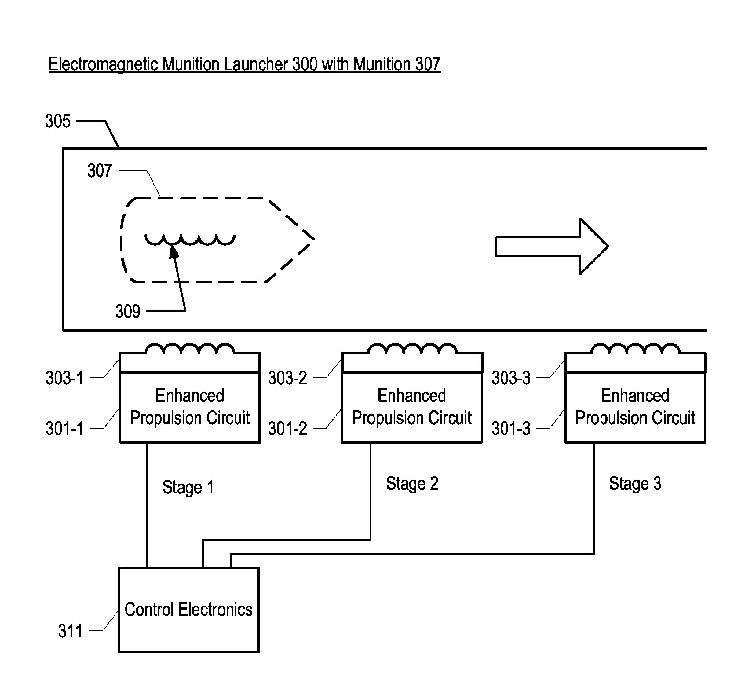
[0047]FIG. 3 depicts the salient elements of electromagnetic munition launcher 300 according to the present invention; munition 307 is also shown. Electromagnetic munition launcher 300 comprises: enhanced propulsion circuits 301-j, where j=1, 2, 3; launch tube 305; and control electronics 311. Each propulsion circuit 301-j comprises propulsion coil 303-j, where j=1, 2, 3. Enhanced propulsion circuit 301-j is described in more detail in respect to FIGS. 5 through 8.

[0048]Electromagnetic munition launcher 300 is illustrated with three stages—1, 2, and 3—each stage comprising only one enhanced propulsion circuit 301-j, but it will be clear to those having ordinary skill in the art, after reading the present disclosure, how to make and use electromagnetic munition launcher 300 with any number of stages; or with any number of enhanced propulsion circuits 301-j per stage; or with any combination thereof.

[0049]Enhanced propulsion circuit 301-j comprises propulsion coil 303-j and is discuss...

second embodiment

[0056]FIG. 4 depicts the salient elements of electromagnetic munition launcher 400 according to the present invention; munition 407 is also shown. Electromagnetic munition launcher 400 comprises: enhanced propulsion circuits 401-j, where j=1 . . . n; launch tube 405; control electronics 411; and sled 413, which comprises armature circuits 409-k, where k=1 . . . m.

[0057]Electromagnetic munition launcher 400 is illustrated with three stages, 1, 2, and 3, each stage comprising a plurality of enhanced propulsion circuits 401-j. It will be clear to those having ordinary skill in the art, after reading the present disclosure, how to make and use electromagnetic munition launcher 400 with any number of stages; or with any number of enhanced propulsion circuits 401-j per stage; or with any combination thereof.

[0058]Enhanced propulsion circuit 401-j is the same as enhanced propulsion circuit 301-j. In some embodiments, enhanced propulsion circuit 401-j is adapted to the particular architectu...


PUM


Abstract

Apparatus and methods provide thermal management of a propulsion circuit in an electromagnetic munition launcher.

Description

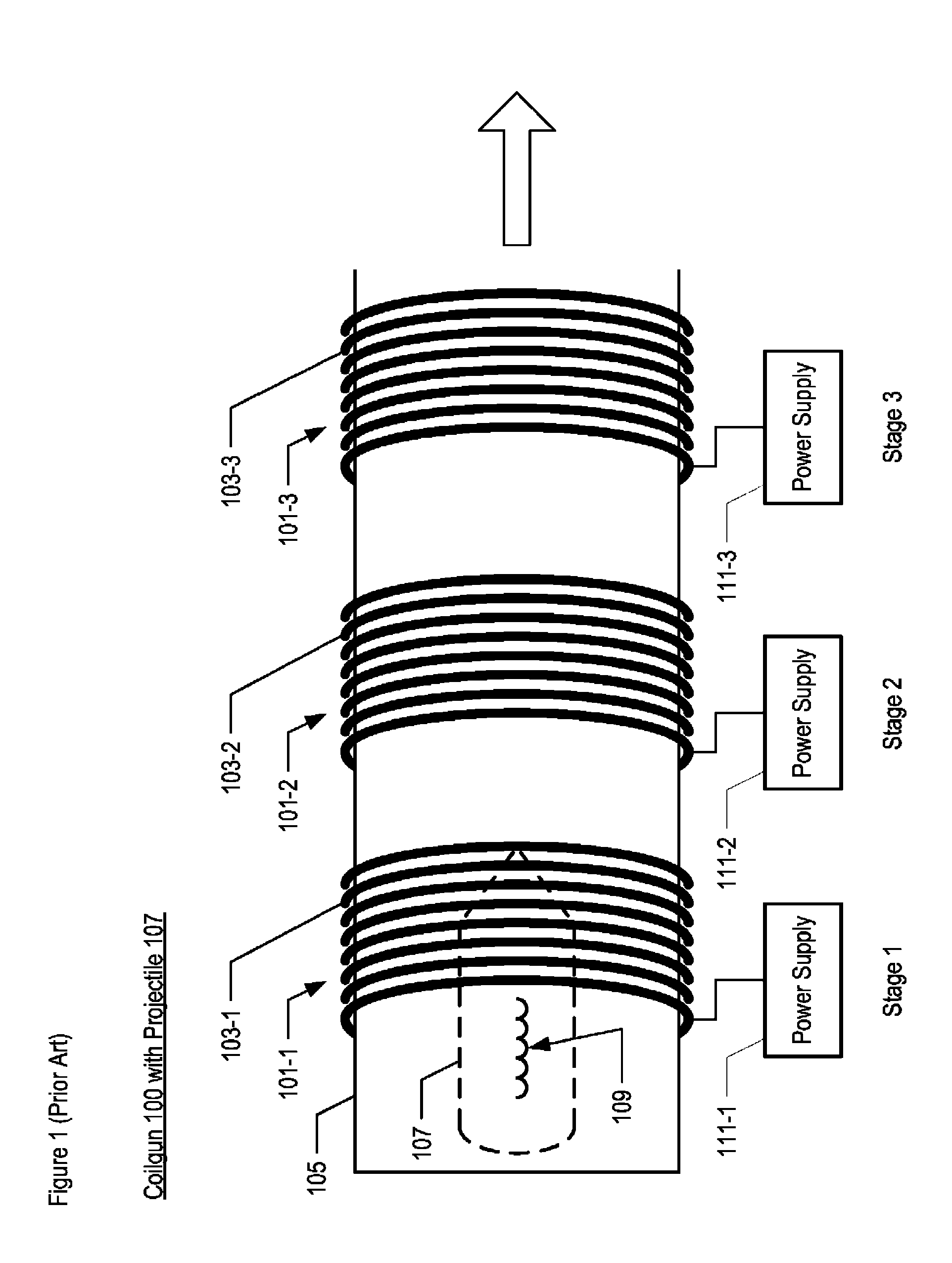
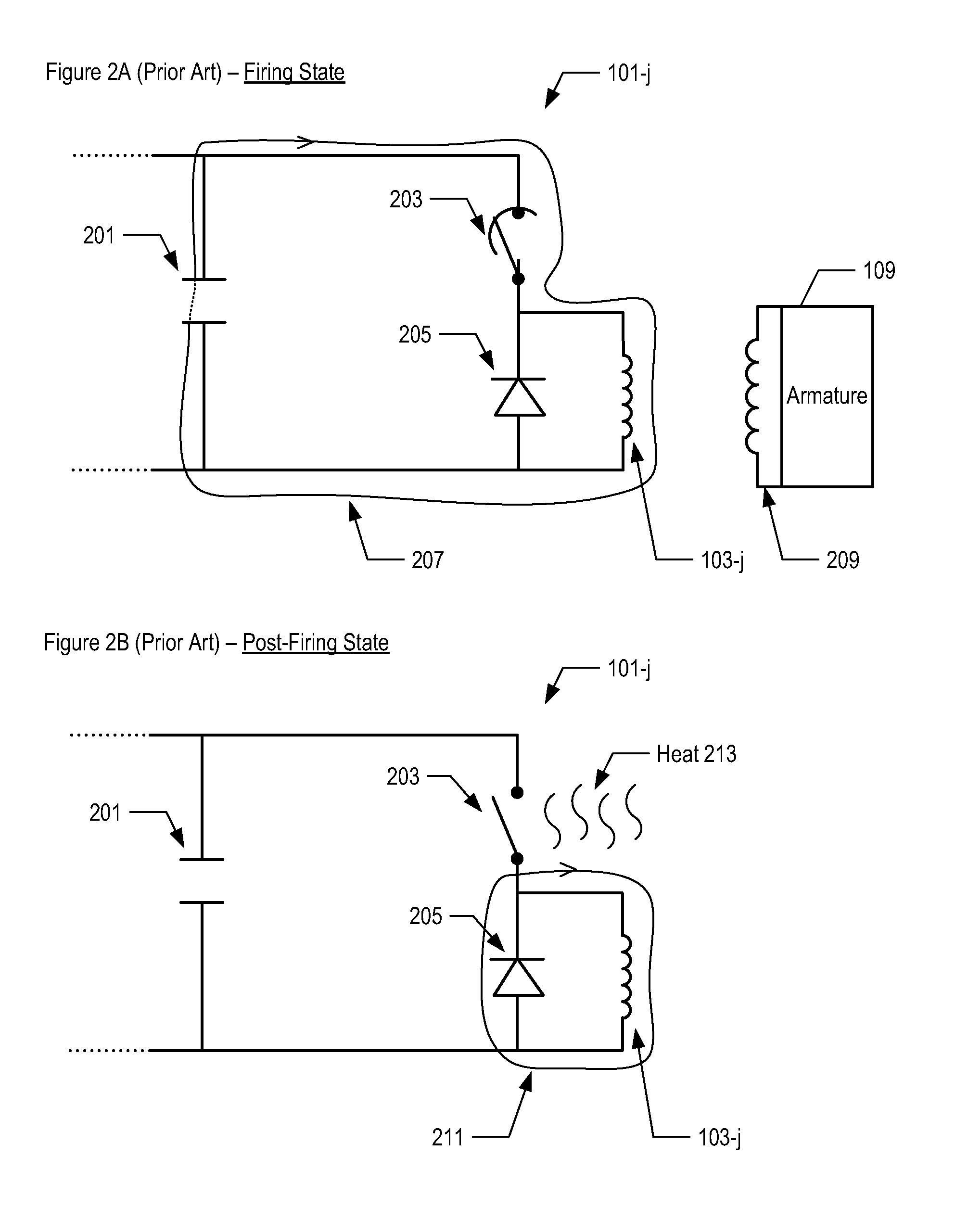
STATEMENT OF RELATED CASES[0001]This case claims priority to U.S. Provisional Application Ser. No. 61 / 523,664, filed on 15 Aug. 2011, and which is incorporated by reference herein.FIELD OF THE INVENTION[0002]The present invention relates to electromagnetic munition launchers in general, and, more particularly, to thermal management thereof.BACKGROUND OF THE INVENTION[0003]An electromagnetic launcher based on induction coilgun technology comprises coil electromagnets. The coils are sequentially arranged along a launch tube to accelerate a projectile to a desired velocity for launch. The coils are powered on and off in sequence to accelerate the projectile and expel it out of the launch tube. The sequentially-arranged coils and their accompanying circuits are commonly known as the “stages” of the coilgun. See FIG. 1.[0004]The coilgun acts as a linear induction motor with respect to the projectile. The projectile is associated with an armature circuit that is part of, or coupled with, ...

Claims


Application Information

Patent Timeline
Patent Type & Authority Patents(United States)
IPC IPC(8): F41B6/00
CPCF41B6/00F41B6/003
Inventor FLOYD, MANDELSMITH, DAVID LEWISKAYE, RONALD J.AUBUCHON, MATTHEW
Owner LOCKHEED MARTIN CORP
Why Eureka
Try Eureka