Variable length shaft

a shaft and variable technology, applied in the direction of rod connections, racket sports, golf clubs, etc., can solve the problems of damage to the shaft and the grip, method is not possible on all clubs, and the skill set required to change the shaft length using this method is usually beyond the ability of the average golfer

Active Publication Date: 2014-03-25
TOPGOLF CALLAWAY BRANDS CORP
View PDF47 Cites 26 Cited by
  • Summary
  • Abstract
  • Description
  • Claims
  • Application Information

AI Technical Summary

Benefits of technology

[0013]In another further embodiment, each of the upper shaft, lower shaft, engaging insert, and locking bar is composed of a composite material, and the grip is affixed to an external surface of the upper shaft. The variable length golf club shaft may further comprise a weighted cap, wherein the upper shaft comprises an opening at an upper end and an opening at a lower end, wherein the opening at the lower end receives the lower shaft, and wherein the opening at the upper end receives the weighted cap. Sliding the upper shaft along the lower shaft may adjust an overall length of the variable length golf club shaft over a range of 3 inches. In a further embodiment, the upper shaft may comprise a slit along a longitudinal axis to accommodate sliding along the lower shaft, and the lower shaft may comprise a locating clip that mates with the slit and prevents the upper shaft from twisting when it slides along the lower shaft.
[0015]In a further embodiment, the plurality of holes may comprise at least ten holes each on at least two opposing sides of the lower shaft wall, and the interior surface of the upper shaft may comprise at least three protrusions each on at least two opposing sides of the interior surface. The plurality of holes may be arranged along a longitudinal axis of the lower shaft, and the protrusions may be arranged along the longitudinal axis of the upper shaft, and sliding the upper shaft along the lower shaft may adjust an overall length of the variable length golf club shaft over a range of 3 inches. The upper shaft and lower shaft may each be composed of a composite material, and a grip may be affixed to the exterior surface of the upper shaft. The variable length golf club shaft may further comprise a weighted cap received by an opening at the upper end of the upper shaft.

Problems solved by technology

It also causes damage to the shaft and the grip.
This method is not possible on all clubs, however, as the head must have hardware that allows for removal of the shaft and replacement with a new shaft without damaging the head.
The skill set required to change the shaft length using this method is usually beyond the abilities of the average golfer, so the golfer would need to seek the services of a golf club fitter or technician to have their club length changed.
The second method requires the golfer to buy an entirely new shaft at a different length, which can be very expensive, and also may require the golfer to retain a golf club fitter or technician to replace the shaft.
Ultimately, the two methods described above require an inventory of spare components and above average technical skill, particularly with regard to the first method.

Method used


Image

  • Variable length shaft
  • Variable length shaft
  • Variable length shaft

Examples


first embodiment

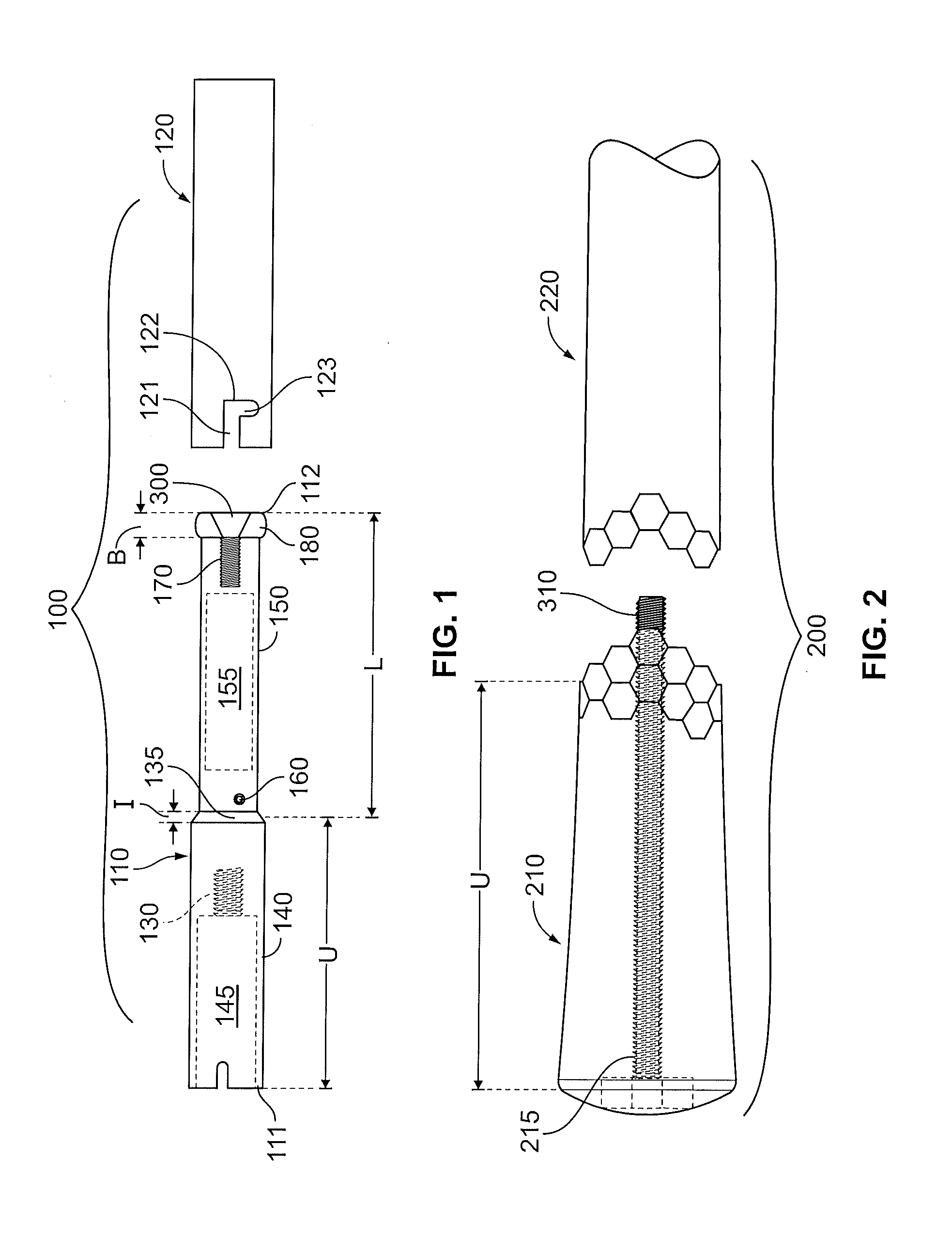
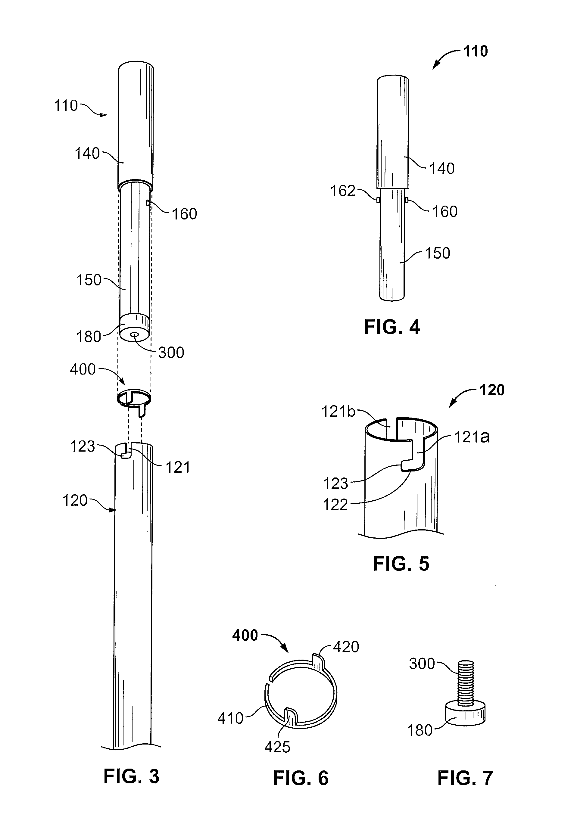
[0042]FIGS. 1-9 show the present invention. This embodiment comprises a two-part shaft 100 having upper 110 and lower 120 sections, a two-part grip 200 having upper 210 and lower 220 sections, and a locating clip 400 to secure the upper shaft section 110 to the lower shaft section 120. In this embodiment, a user can remove the upper shaft and grip sections 110, 210 from the lower shaft and grip section 120, 220 and replace them with upper shaft and grip sections 110, 210 having different overall lengths and / or weights.

[0043]As shown in FIGS. 1, 3, and 4, the upper shaft 110, which has proximal 111 and distal ends 112 and proximal and distal portions 140, 150, includes a threaded hole 130 located in the proximal portion 140. As shown in FIG. 1, the threaded hole 130 extends from a hollow interior portion 145 located in the proximal portion 140 of the upper shaft 110 toward the distal portion 150. In an alternative embodiment, the threaded hole 130 may extend from the furthest extent ...

second embodiment

[0052]the present invention, which does not require multiple upper shaft or grip pieces having varying lengths, is shown in FIGS. 11 and 12A-12C. A variable length shaft 600 has an upper shaft piece 610 and a lower shaft piece 660. The upper shaft piece is similar in structure to the upper shaft piece 110 shown in FIG. 1, as it has an upper portion 620, a lower portion 630, and one or more pins 640, 642 located on the lower portion 630. The lower shaft piece 660 has at least one notch 670 sized to hold the one or more pins 640, 642. In this embodiment, the at least one notch 670 has more than one side channel 672, 674, 676, 678, within which the pins 640, 642 can fit.

[0053]To assemble this embodiment, the lower portion 630 of upper shaft piece 610 is inserted in the hollow interior of the lower shaft piece 660 such that the pins 640, 642 slide into the at least one notch 670. When the combination of the lower and upper shaft pieces 610, 660 equals a desired overall shaft length, the...

third embodiment

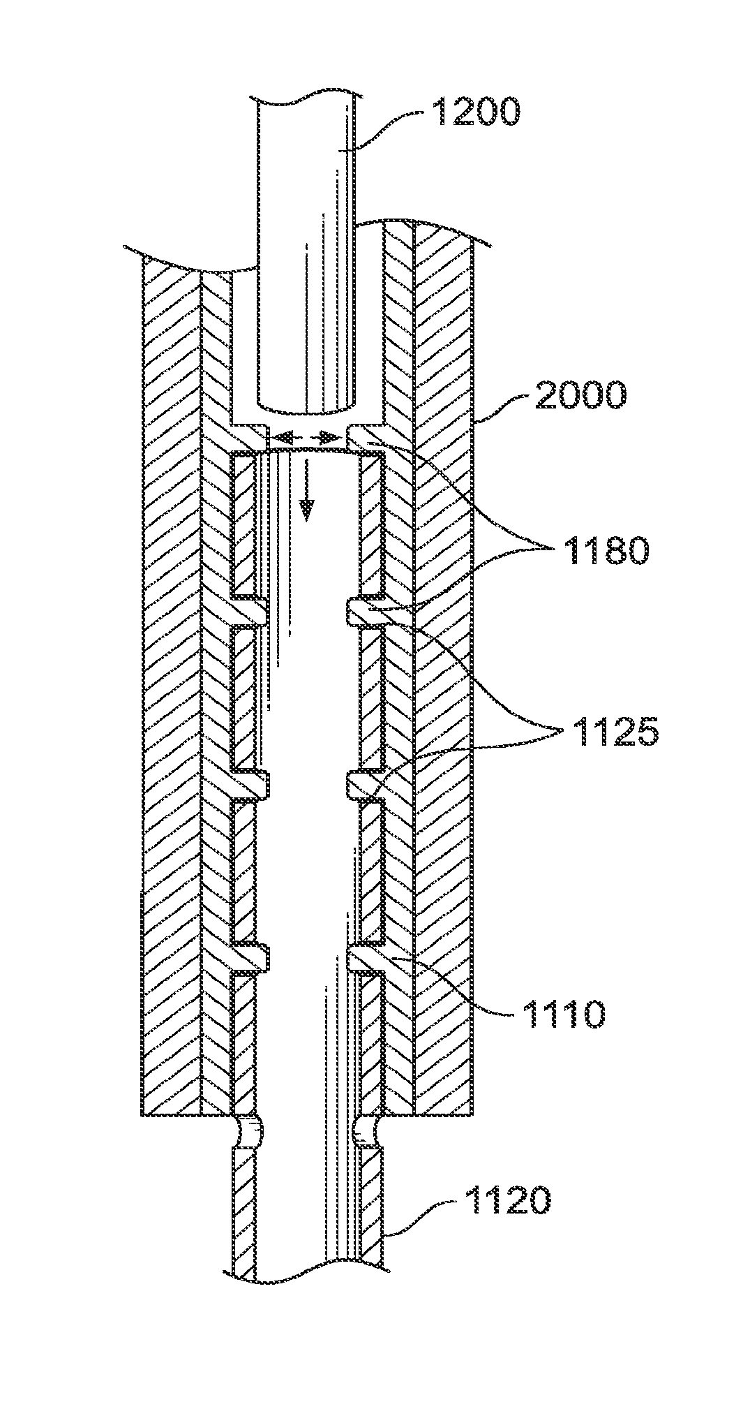
[0054]the present invention, which also does not require multiple upper shaft or grip pieces having varying lengths, is shown in FIGS. 13, 14A, 14B, 15A, and 15B. A variable length shaft 1000 has an upper shaft piece 1110 and a lower shaft piece 1120, each of which is hollow. The upper shaft piece 1110 has an open upper end 1111, an open lower end 1112, and a plurality of holes 1115 that extend through the wall of the upper shaft piece 1110, preferably on at least two, opposite sides of the upper shaft piece 1110 proximate the open lower end 1112. The external surface of the upper shaft piece also has a grip 2000 affixed to it, preferably by an adhesive.

[0055]The lower shaft piece 1120 also has an open upper end 1122, a lower end 1121 that can be engaged with a golf club head 50, and a plurality of holes 1125 that extend through the wall of the lower shaft piece 1120, preferably on at least two, opposite sides of the lower shaft piece 1120, proximate the open upper end 1122 of the l...


PUM


Abstract

A variable length golf club shaft is disclosed herein. The variable length shaft includes a hollow lower shaft with a plurality of holes, a hollow upper shaft with at least one protrusion extending from an inner surface that is sized to fit within the plurality of holes, and an unlocking bar. The shaft length can be adjusted by sliding the upper shaft over the lower shaft and using the unlocking bar to release the protrusion from the holes to allow overall shaft length adjustments. In another embodiment, the variable length shaft includes a hollow lower shaft, a hollow upper shaft, an engaging insert, and a locking bar.

Description

CROSS REFERENCES TO RELATED APPLICATIONS[0001]The present application is a continuation-in-part of U.S. patent application Ser. No. 13 / 009,710, filed on Jan. 19, 2011, which claims priority to U.S. Provisional Patent Application No. 61 / 422,982, filed on Dec. 14, 2010.STATEMENT REGARDING FEDERALLY SPONSORED RESEARCH OR DEVELOPMENT[0002]Not ApplicableBACKGROUND OF THE INVENTION[0003]1. Field of the Invention[0004]The present invention relates to a variable length shaft assembly that allows for quick, semi-permanent length adjustments. More specifically, the present invention relates to a variable length shaft whose length can be adjusted in a short period of time with the use of a simple tool and without the use of many different components.[0005]2. Description of the Related Art[0006]Customization of golf clubs to help golfers attain better shots has become a popular and more prevalent practice in recent years. Golf club manufacturers and designers have devised various features to al...

Claims


Application Information

Patent Timeline
Patent Type & Authority Patents(United States)
IPC IPC(8): A63B53/16
CPCA63B2053/005A63B53/10A63B53/16A63B53/12A63B53/14A63B60/22A63B53/005Y10T403/32483A63B60/28A63B60/0085
Inventor WALL, JR., BROADUS, PERRY
Owner TOPGOLF CALLAWAY BRANDS CORP
Why Eureka
Try Eureka