Apparatus for metal cutting and welding

a technology for cutting and welding metals, applied in the direction of aluminum-thermic welding apparatus, manufacturing tools, non-electric welding apparatus, etc., can solve the problems of logistical and operational limitations in both foreign and domestic situations, and achieve the effects of increasing the brittleness of rm and gunpowder, improving efficiencies, and more energetic reaction to force applied

Active Publication Date: 2014-03-25
BLEICKEN ERIC +2
View PDF17 Cites 3 Cited by
  • Summary
  • Abstract
  • Description
  • Claims
  • Application Information

AI Technical Summary

Benefits of technology

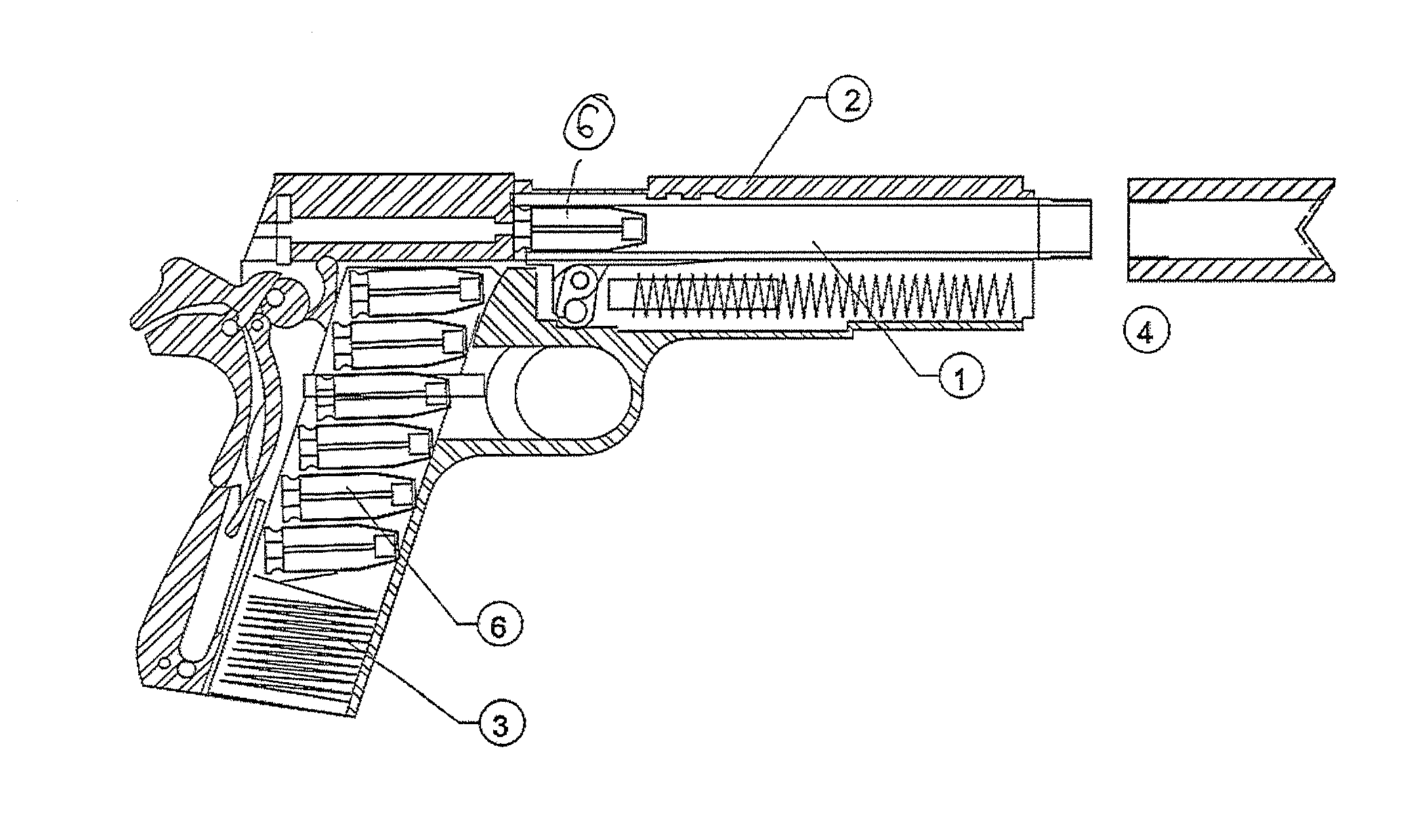
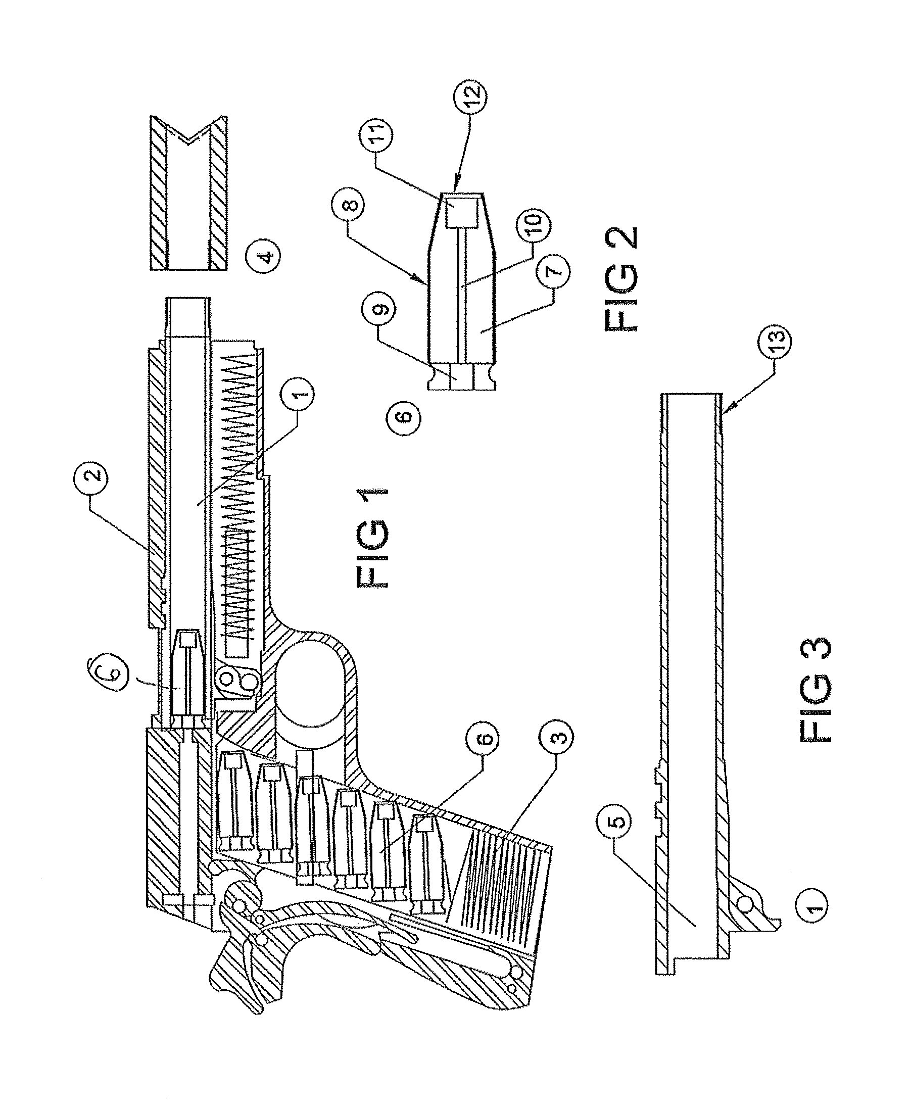
[0011]Other embodiments, while useful for RM, improve the firearm itself. The first embodiment is a cartridge that is fed into the breech from the gun's magazine or clip when the muzzle is temporarily fitted with a cutting or welding nozzle. In this case, the gun's breech, barrel and detachable nozzle should be manufactured from heat resistant material such as ceramic, or at least its bore may be fabricated of such material, including the option of using a composite, and / or a ceramic-composite combination, provided such material is either or both of refractory and insulative (at least in comparison to metal).
[0013]These embodiments of the device of the present invention are able to cut and spot-weld metals; however specific RM formulations and nozzle configurations for particular applications are likely to be different. It is further expected that nozzles and RM may be specifically designed for rapid burning as well as slow burning if and when quiet operation is essential. Another embodiment of the invention utilizes the thermal insulator characteristics of some ceramics to increase the brisance of RM and gunpowder to improve their efficiencies. In this embodiment, either the bore or the entire barrel is made of a ceramic material. The ceramic material is refractory and / or insulative more than conductive, unlike a conventional metal used to make a gun barrel. As a result, the heat of reaction is reflected by the ceramic of the bore / barrel back into the combustion reaction instead of being absorbed by the barrel, resulting in a more energetic reaction for the force applied to the projectile. A further embodiment of the invention utilizes a barrel with oval rifling. The oval rifling reduces the risk of stress concentrators, while improving the flight characteristics of a projectile by eliminating engraved edges which could interact with air. Yet another embodiment of the invention is a barrel with a taper to the bore. In a gun barrel with a uniform barrel internal cross section, a projectile, once deformed by bore rifling, hysteresis reduces the gas seal moving down the bore. The introduction of a taper to the bore increases the likelihood of establishing a tight projectile fit along the entire length of the barrel, thereby enhancing the energy behind the projectile as it exits the gun. Yet another embodiment of the invention allows the rifling to possess an accelerating spin. This can protect projectiles containing sensitive materials, and can allow specific shear rates for RM gasses within the bore.

Problems solved by technology

Some potentially related systems are explosively driven systems that are of limited value in clandestine or covert operations where minimal noise is critical and explosives create a variety of logistical and operational limitations in both foreign and domestic situations.

Method used


Image

  • Apparatus for metal cutting and welding
  • Apparatus for metal cutting and welding
  • Apparatus for metal cutting and welding

Examples


second embodiment

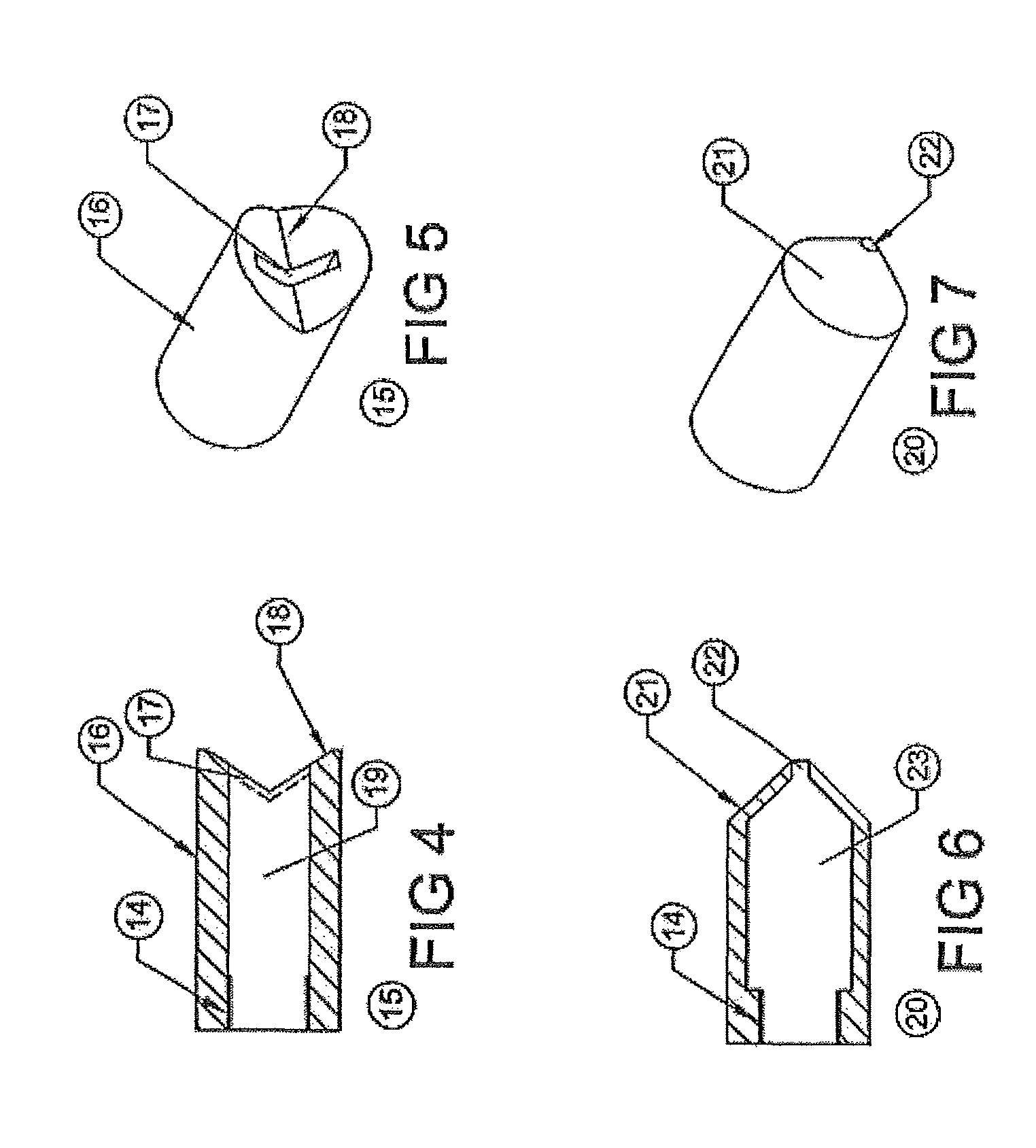
[0038]a cutting / welding device of the present invention is shown in FIG. 8 as a gun. The gun and / or components and variants of components thereof are shown in FIGS. 8-12 and include the gun barrel 1, the breech 5, a muzzle loading cutting component 24, a heat resistant tube 26, an impact-initiated primer 27, a cutting nozzle 28, an inert breech plug 29, a nozzle plug 30, which may be frangible or ablative, a muzzle loading tack welding device 31, the RM 7, the hollow flame tube 10, the RM ignition initiator 11, the slot opening 17 for the cutting component 24, and the pointed end 21 and the internal chamber 23 for the muzzle loading tack welding device 31.

[0039]The heat resistant tube 26 is configured to extend substantially the entire length of the gun barrel 1 and extending through the breech 5, is fitted with a center fire primer 27 or impact initiated electronic device at the point where the gun's hammer can ignite the device corresponding in that manner to the operation of the ...

first embodiment

[0042]As seen in FIG. 10, the tube 26 is elongate with the nozzle 28 affixed thereto. The end of the device 24 that extends into the breech is provided with the primer 27 that is exploded into the flame tube 10 that extends longitudinally through the center of the device 24 and prevents the ignition of the surrounding RM 7. At the muzzle end of the device 24, and behind the cutting nozzle 28 is the RM Initiator 11 that activates the RM 7. As described in the first embodiment above, the nozzle 28 has a cylindrical outer shape with the V shaped or concave front face 18 with the slot 17 situated 90° through the center of the face 18. The slot 17 may be plugged with plug 30, which may be a frangible or ablative material to protect the interior of the device 24 from environmental hazards during storage.

[0043]Like the previously described embodiment, the cutting nozzle 28 may have a slotted or some other configuration designed to increase the cutting efficiency of the torch established up...


PUM

PropertyMeasurementUnit
stress concentrationsaaaaaaaaaa
heat resistantaaaaaaaaaa
heataaaaaaaaaa

Abstract

A device for either or both of metal cutting and metal welding. The device is configured to a standard service side arm and other guns and / or other types of tools to cut and / or weld metals for the purposes of breaching and welding metals in a range of applications, including in air and underwater, without degrading the primary purposes of the gun or other tools. In one embodiment, the device includes a reactive material cartridge and a nozzle adapted for attachment to a muzzle. In another embodiment, the device includes a muzzle-loading tube including the reactive material and a nozzle configured to shape the reactive material exiting the tube.

Description

CROSS-REFERENCE TO RELATED APPLICATION[0001]This application is a nonprovisional and claims the priority benefit of U.S. provisional patent application Ser. No. 61 / 520,593, filed Jun. 13, 2011, entitled “METAL CUTTING / TRACK WELDING KIT FOR SERVICE SIDEARM OR OTHER GUN.” The entire content of the priority application is incorporated herein by reference.BACKGROUND OF THE INVENTION[0002](1) Field of the Invention[0003]This invention relates to devices for cutting and welding metal. More particularly, this invention relates to devices for cutting and welding metal using reactive materials.[0004](2) Description of the Prior Art[0005]Military, law enforcement, and emergency response personnel have a longstanding need for breaching locks, doors and other devices to allow access to closed areas and spaces in time sensitive situations. Similarly, these same communities and other officials who carry guns require a means to instantly tack weld things to metal objects in air or underwater such ...

Claims


Application Information

Patent Timeline
Patent Type & Authority Patents(United States)
IPC IPC(8): B23K7/00
CPCF41C27/00B23K20/00F41A35/00F42B3/22F41C27/20F42B12/36B23K23/00F41A21/32B23K7/00B23K5/22B23K20/06
Inventor BLEICKEN, ERICBARNETTE, DARRELBYRON, DAVID
Owner BLEICKEN ERIC
Why Eureka
Try Eureka