Ratchet adjustment system

a ratchet and adjustment technology, applied in the field of ratchet adjustment system, can solve the problems of reducing the adhesiveness of parts, cumbersome adjustment of the ratchet with only one hand, etc., and achieve the effect of convenient adjustment, easy slide and convenient adjustmen

Inactive Publication Date: 2014-04-01
DURAFLEX HONG KONG
View PDF40 Cites 14 Cited by
  • Summary
  • Abstract
  • Description
  • Claims
  • Application Information

AI Technical Summary

Benefits of technology

[0012]One advantage of the invention is that the mechanism can be adjusted easily using only one hand. All that is required is to push the locking mechanism along the elongated adjustment strip with the minimum amount of force required for either the forward or rearward direction. To facilitate this adjustment, the top side of the cover plate can be equipped with a series of raised ridges. These ridges prevent fingers from slipping on the cover plate during adjustment, even when the user is wearing gloves.
[0013]In one embodiment, the teeth are located along longitudinal edges of the elongated adjustment device and the locking device comprises two longitudinally extending springs arranged on the base plate so as to engage the teeth when the locking device is moved along the elongated adjustment strip. Here, the strip is attached to the cuff only along the longitudinal axis of the strip, so that the teeth of the strip are not connected to the cuff. This way, the brackets of the locking device can slide under the teeth and keep the locking device in contact with the strip at all times.
[0014]In another embodiment, the teeth are facing upward along an expanse of the elongated adjustment strip, and the locking device comprises a resilient arm that engages the teeth when the locking mechanism is slid along the elongated adjustment strip. In this embodiment, there can be one or multiple rows of teeth along the strip. The brackets on the base plate can engage around edges of the strip to allow the locking mechanism to slide along the strip.
[0015]In another embodiment, the adjustment strip has a plurality of gears along an expanse of the adjustment strip, disposed along the longitudinal expanse of the strip, with a guide channel in between. The gears are positioned on supports that raise them above the adjustment strip. Each support is wider at its longitudinal ends than in the middle, creating an indentation in the middle of each support, facing the longitudinal sides of the strip. The locking device is disposed on a base and consists of a guide ridge running along the center of the base, and a plurality of brackets disposed on either side of the ridge. The brackets each have an engaging tooth aimed inwardly toward the guide ridge. The gears can be fed into the locking device so that the ridge runs in the guide channel and the teeth of the brackets engage the supports under the gears to keep the strip and base connected. The gears have a wide top section that rests on top of the teeth of the brackets to keep the strip and base connected. The brackets are configured so that it is easier to slide the strip in a forward direction into the locking device rather than backwards out of the locking device. This is accomplished in this embodiment by the teeth of the brackets, which are formed as a ratchet system so that each tooth has a forward side facing a forward direction and a rearward side facing a rearward direction. The length of each of the forward sides is greater than a length of each of the rearward sides so that an angle created between a longitudinal axis of the elongated adjustment strip and the forward side is smaller than an angle between the longitudinal axis and the rearward side of each tooth.
[0016]This ratcheting system makes it easier to slide the strip and base together in the forward direction, because the bracket slides at a smaller angle than in the rearward direction, causing a more gradual build-up of tension on the bracket. Once the bracket reaches a center of each gear, the tension releases, as the indentation in the gear's center allows the bracket to expand and relax into a resting position in the indentation. Further movement in the forward direction requires a certain minimum amount of force to be applied. Movement in the backward direction requires a higher minimum amount of force, because of the larger angle of the tooth in the backward direction forces a greater initial flex of the bracket.
[0017]In one embodiment, there are at least two brackets positioned on either side of the guide ridge, and the gears are arranged in two parallel rows in on the strip.

Problems solved by technology

The disadvantage to using a buckle is that the buckle is very cumbersome to adjust with only one hand, which is necessary in the case of a sleeve cuff.
The disadvantage to using the hook and loop type closure is that the rough surfaces on the closure parts attract a significant amount of debris, which can be unsightly and decrease the adhesiveness of the parts.

Method used


Image

  • Ratchet adjustment system
  • Ratchet adjustment system
  • Ratchet adjustment system

Examples


Embodiment Construction

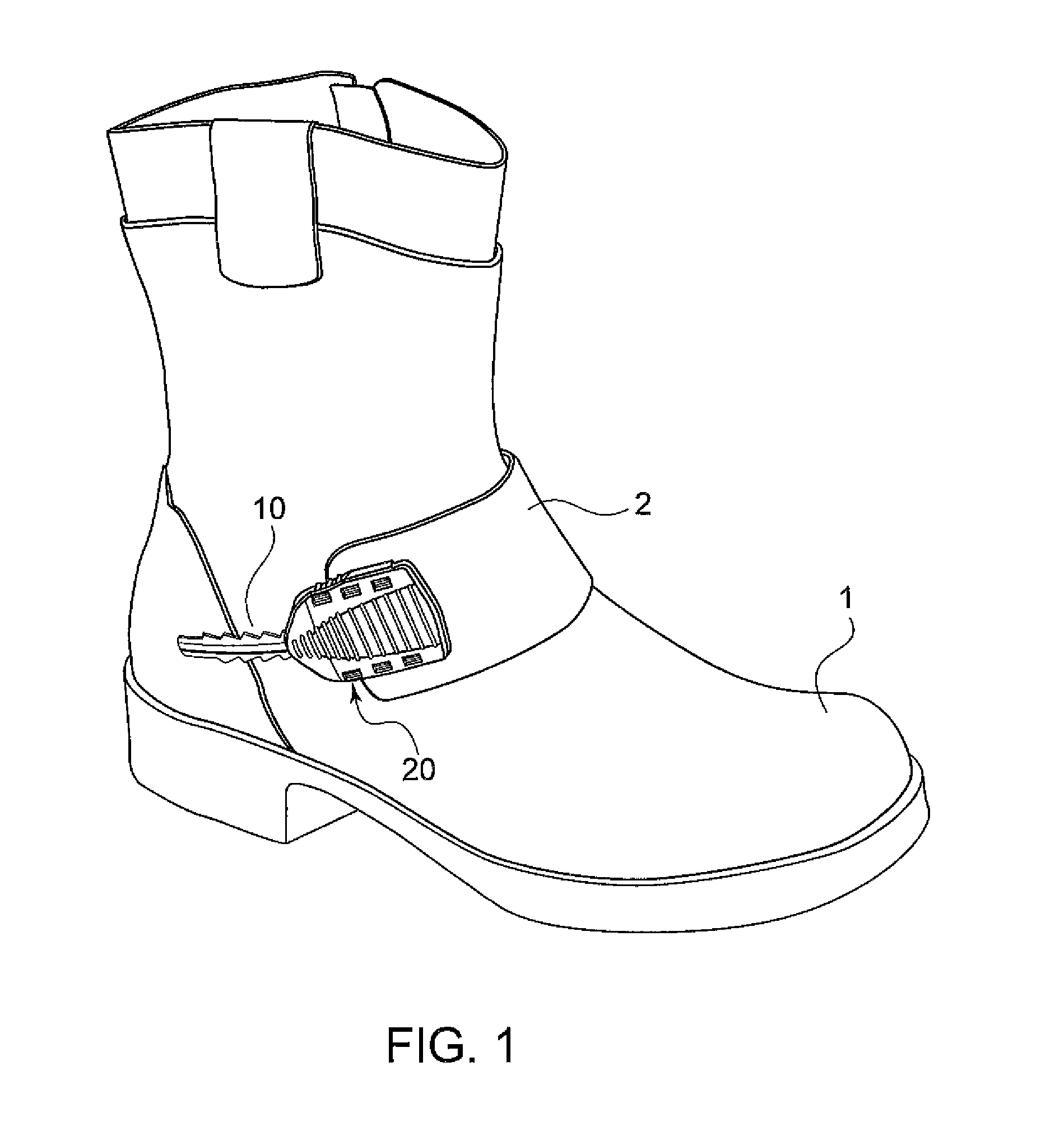
[0042]Referring now in detail to the drawings, FIG. 1 shows a view of the view of the system according to the invention installed on a boot 1. The system comprises an elongated adjustment strip 10 and a locking mechanism generally designated as 20 attached to a strap 2 of boot 1. Locking mechanism 20 slides along adjustment strip 10 to tighten or loosen boot 1 as desired. The structure and function of the system is explained below with reference to the remaining Figures.

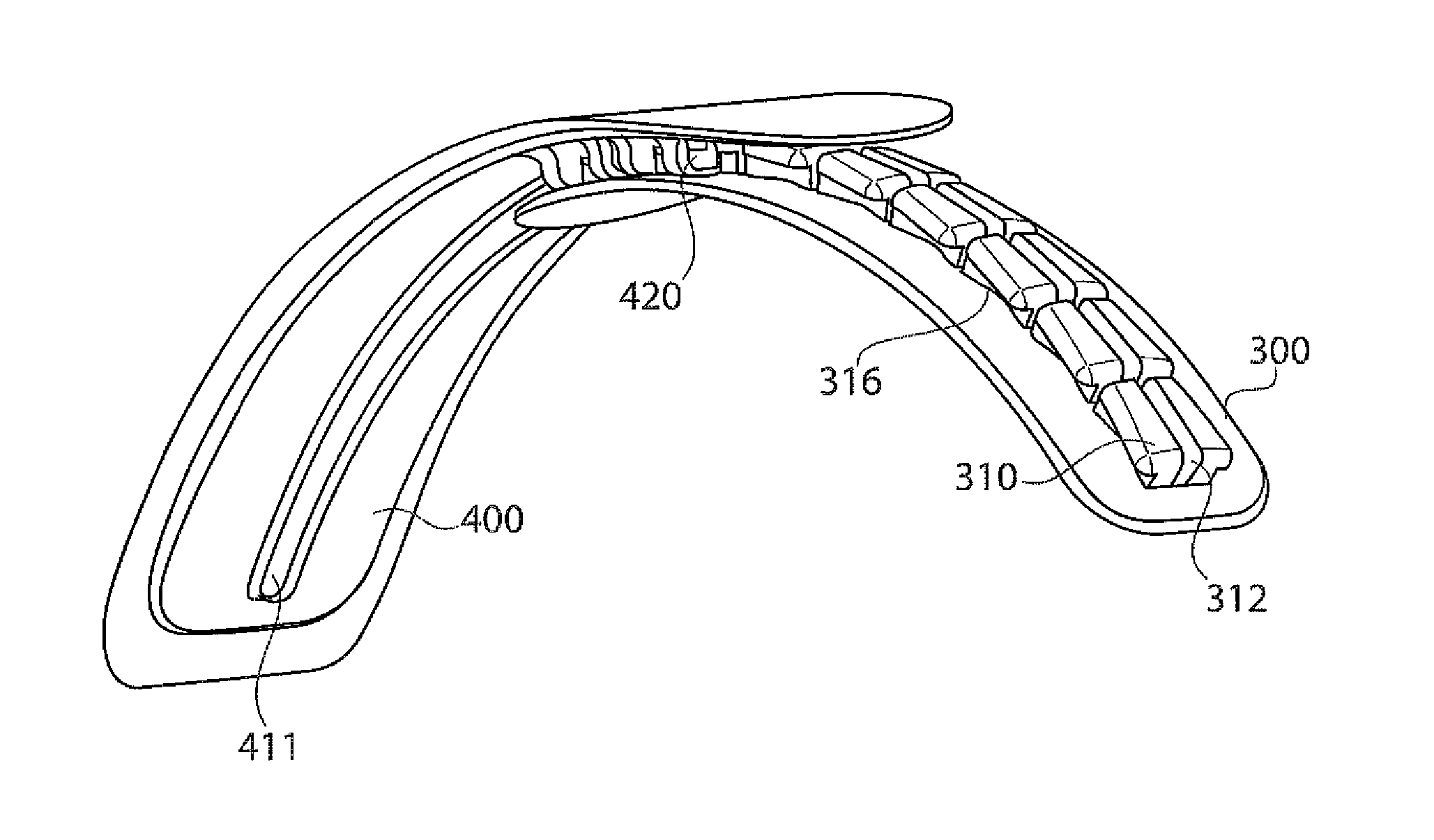
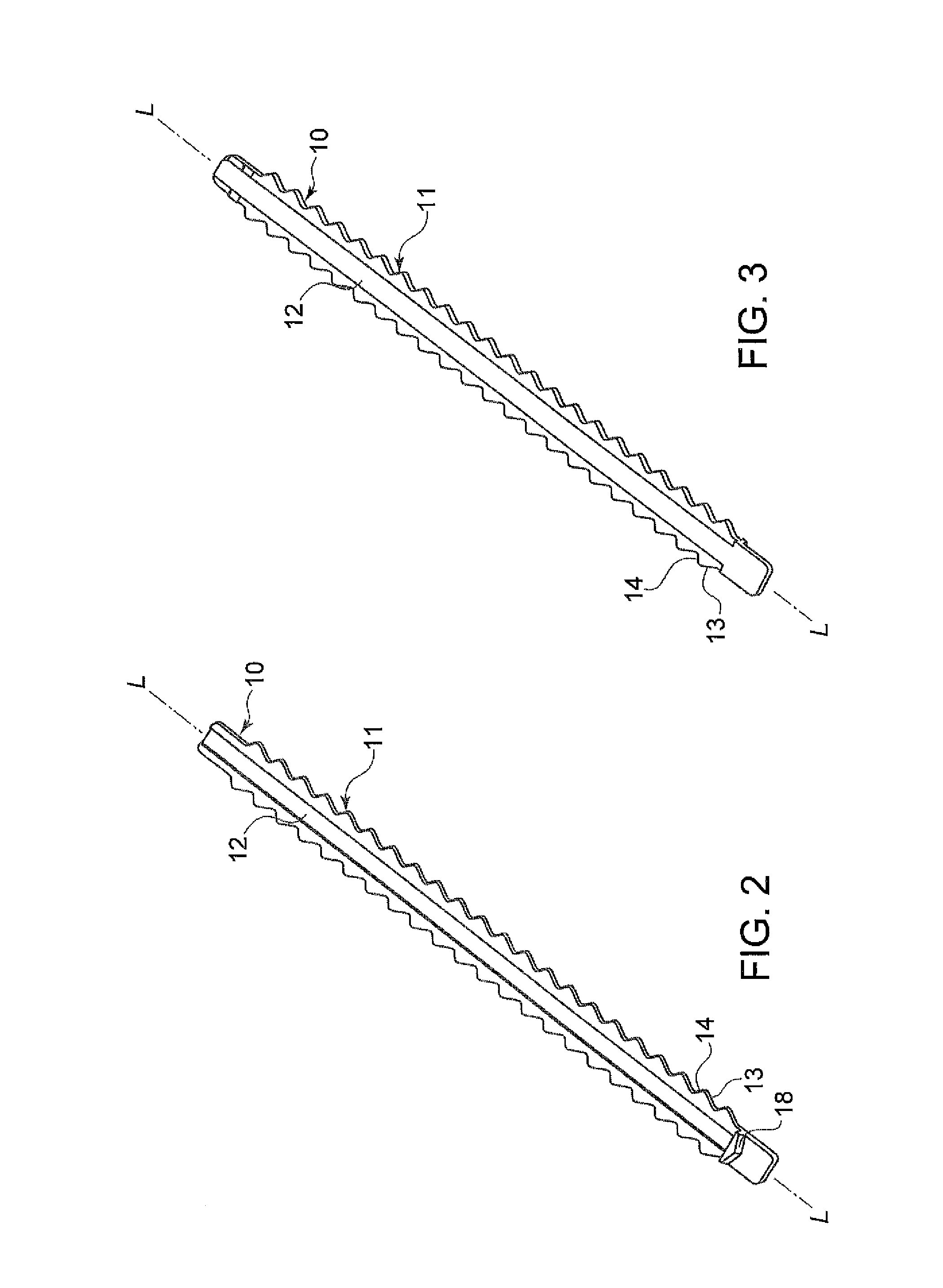
[0043]FIGS. 2 and 3 show the elongated adjustment strip 10 according to one embodiment of the invention. The strip has a set of teeth 11 extending along each of the two longitudinal sides of strip 10. A central portion 12 of strip 10 is recessed on the top surface as shown in FIG. 2 and protrudes from the bottom surface as shown in FIG. 3. This way, the central portion 12 can be attached to an article along the bottom surface of strip 10 while leaving teeth 11 free. Each one of teeth 11 has a forward side 13 facing a...


PUM


Abstract

An adjustment system for adjusting the width of a cuff has an elongated adjustment strip having a set of longitudinally extending teeth. Each tooth has a forward side and a rearward side. A length of each forward side is greater than a length of each of the rearward sides so that an angle between a longitudinal axis of the strip and the forward side is less than an angle between the longitudinal axis and the rearward side of each tooth. There is a locking mechanism formed by a base plate having a locking device on an underside and a guide for slidably connecting the locking mechanism to the strip. The tooth and the locking device are configured so that the locking device can be moved forward along the strip using only a small amount of force, and can then be moved rearward using a larger amount of force.

Description

CROSS REFERENCE TO RELATED APPLICATIONS[0001]This application is a continuation-in-part under 35 U.S.C. §120 of U.S. patent application Ser. No. 12 / 930,534 filed on Jan. 10, 2011, the disclosure of which is herein incorporated by reference.BACKGROUND OF THE INVENTION[0002]1. Field of the Invention[0003]This invention relates to an adjustment system for increasing and decreasing the circumference of an article, such as a sleeve cuff or footwear. In particular the invention relates to an adjustment system using a ratcheting device to adjust the width of the article.[0004]2. The Prior Art[0005]In some articles of apparel, such as jacket sleeve cuffs and pant cuffs in athletic clothing, the cuff width needs to be adjusted to be more secure around the wrist or ankle of the user. Traditionally, this adjustment was accomplished via a strap that could be tightened around the cuff, either with a buckle or a hook-and-loop type closure, such as VELCRO.®[0006]The disadvantage to using a buckle ...

Claims


Application Information

Patent Timeline
Patent Type & Authority Patents(United States)
IPC IPC(8): A44B11/02A44B11/10A43C11/12
CPCA43C11/146A43C11/1486A41F1/008Y10T24/2185Y10T24/45246
Inventor FRAZE, GARY
Owner DURAFLEX HONG KONG
Why Eureka
Try Eureka