Mounting system for solar module array

a solar module and mounting system technology, applied in the direction of heat collector mounting/support, pv power plants, light and heating equipment, etc., can solve the problems of solar mounting systems in which the solar modules must be slid along the rails, the installation of solar modules may be more difficult, and the replacement of solar modules may be difficul

Active Publication Date: 2014-04-01
SUNPOWER CORPORATION
View PDF45 Cites 85 Cited by
  • Summary
  • Abstract
  • Description
  • Claims
  • Application Information

AI Technical Summary

Benefits of technology

[0012]Occasionally, a solar module that is surrounded by other solar modules in an array, is damaged and thus requires replacement. Solar mounting systems in which the solar modules must be slid along rails present a significant difficulty when the need arises for replacing a solar module. In this situation, the rail-mounted array must be partially disassembled, i.e., the undamaged solar modules adjacent to the damaged module must be slid off of the rail first before the damaged module can be removed. The replacement module is then slid along the rails back into place. In a large array, this method of repair can require the removal of many solar modules. Thus, a solar module mounting system that can allow individual solar modules to be removed from an array, without removing adjacent modules can provide a significant labor savings.
[0014]Thus, in accordance with at least some embodiments disclosed herein, a mounting system for mounting solar modules to a fixed structure such as a roof can be configured to allow solar modules to be removed from an array of solar modules without the need to slide adjacent solar modules off of rails. Further benefits can be achieved by configuring a solar module mounting system such that the engagement portions of the mounting system can be removed by engaging upwardly facing fasteners. Additionally, further benefits can be achieved by configuring a solar module mounting system such that vertical adjustments can be made to the mounting height of solar modules by engaging adjustment mechanism with an upwardly facing engagement portion.
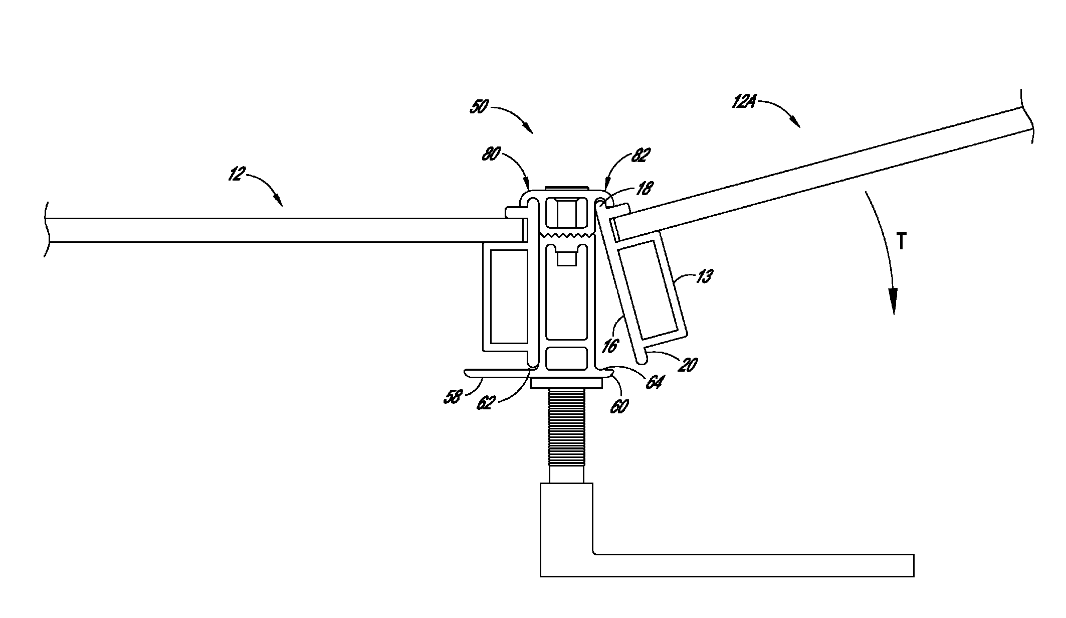
[0015]In accordance with at least one embodiment, a height-adjustable roof anchor for solar modules can comprise a base having a hole therein, the hole comprising an inner wall. A height adjustment member can have an upper portion configured to engage at least one solar module, the height adjustment member extending from the hole of the base and upwardly away from the base, the height adjustment member having an annular groove formed around the circumference of the rod, the annular groove positioned within the hole. A locking portion can engage the annular groove so as to retain the height adjustment member in the hole and allow the height adjustment member to rotate about a rotational axis, wherein the height adjustment member is configured to adjust a height of the at least one solar module during rotation about the rotational axis.
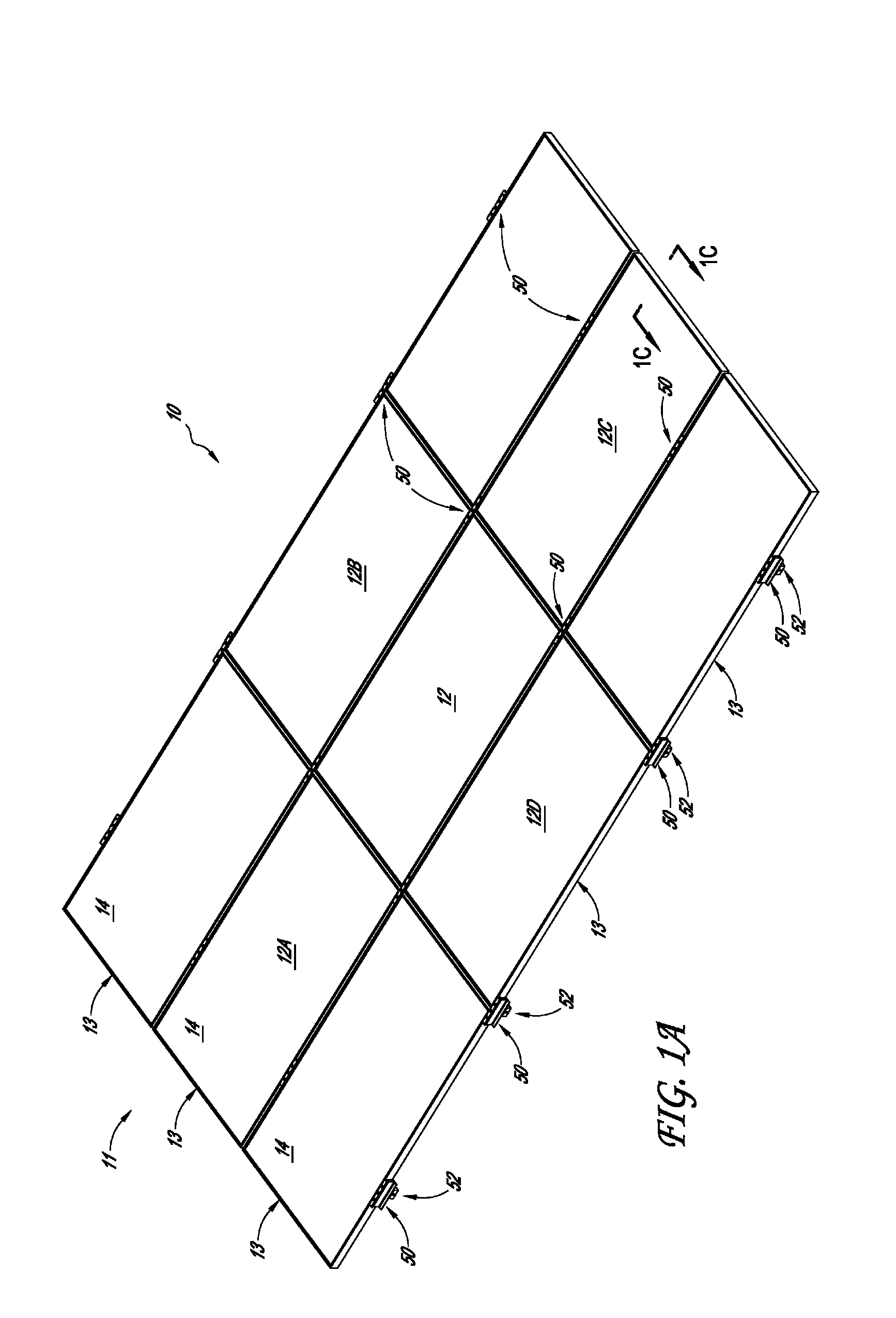
[0021]In accordance with another embodiment, a solar array can comprise at least first, second, third, fourth, and fifth solar modules, each solar module having at least four sides, wherein the first, second, third, and fourth solar modules are respectively disposed adjacent to the four sides of the fifth solar module. Additionally, the array can include braces for removal of the bracing the juxtaposed sides of the solar modules to each other so that the fifth solar module can be disconnected from the first, second, third, and fourth solar modules and lifted upwardly without the need to slide the fifth solar module laterally.

Problems solved by technology

By contrast, many residential roofs may be sloped or angled such that placement of a solar module may be more difficult due to gravitational forces imposed on the angled modules.
Occasionally, a solar module that is surrounded by other solar modules in an array, is damaged and thus requires replacement.
Solar mounting systems in which the solar modules must be slid along rails present a significant difficulty when the need arises for replacing a solar module.
The Zep Solar mounting system noted above, also suffers from difficulties.
This procedure can be particularly difficult when a worker is attempting to reach solar module that is surrounded by other modules, and thus in a position in which it is difficult to achieve the alignment of the special tool and the engagement face of the rotatable fastener.

Method used


Image

  • Mounting system for solar module array
  • Mounting system for solar module array
  • Mounting system for solar module array

Examples


Embodiment Construction

[0037]The following detailed description is merely illustrative in nature and is not intended to limit the embodiments of the subject matter or the application and uses of such embodiments. As used herein, the word “exemplary” means “serving as an example, instance, or illustration.” Any implementation described herein as exemplary is not necessarily to be construed as preferred or advantageous over other implementations. Furthermore, there is no intention to be bound by any expressed or implied theory presented in the preceding technical field, background, brief summary or the following detailed description.

[0038]“Coupled”—The following description refers to elements or nodes or features being “coupled” together. As used herein, unless expressly stated otherwise, “coupled” means that one element / node / feature is directly or indirectly joined to (or directly or indirectly communicates with) another element / node / feature.

[0039]“Adjust”—Some elements, components, and / or features are des...


PUM

PropertyMeasurementUnit
lengthaaaaaaaaaa
circumferenceaaaaaaaaaa
solar energyaaaaaaaaaa

Abstract

A mounting system for a solar array can include a plurality of couplers that are designed to engage and disengage all modules without the use of rails that are greater than the maximum dimension of a solar module. The couplers can be configured to cooperate with height adjuster mechanisms. Additionally, the couplers can be configured to accommodate the engagement and disengagement of solar modules without the need to loosen or remove fasteners, for example, through a hook and tilt movement.

Description

BACKGROUND OF THE INVENTIONS[0001]1. Field of the Inventions[0002]Embodiments of the subject matter described herein relate generally to devices and systems from mounting solar modules to fixed surfaces such as roofs.[0003]2. Description of the Related Art[0004]Solar power has long been viewed as an important alternative energy source. To this end, substantial efforts and investments have been made to develop and improve upon solar energy collection technology. Of particular interest are residential-, industrial- and commercial-type applications in which relatively significant amounts of solar energy can be collected and utilized in supplementing or satisfying power needs. One way of implementing solar energy collection technology is by assembling an array of multiple solar modules.[0005]One type of solar energy system is a solar photovoltaic system. Solar photovoltaic systems (“photovoltaic systems”) can employ solar panels made of silicon or other materials (e.g., III-V cells such...

Claims


Application Information

Patent Timeline
Patent Type & Authority Patents(United States)
IPC IPC(8): E04D13/18
CPCH01L31/0482H01L31/18Y02E10/50Y02B10/12H01L31/048F24J2002/4672F24J2/5264F24J2/5262F24J2/5207F24J2/5245Y10T29/49355H02S20/23F24J2/5211F24J2/5258F24S25/20F24S25/35F24S25/61F24S25/636F24S25/67F24S25/70F24S2025/6008Y02B10/10Y02E10/47
Inventor DANNING, MATTHEW, G.
Owner SUNPOWER CORPORATION
Why Eureka
Try Eureka