Pontoon tarpaulin system

Active Publication Date: 2005-12-27
JIRAK JERRY D
View PDF17 Cites 13 Cited by
  • Summary
  • Abstract
  • Description
  • Claims
  • Application Information

AI Technical Summary

Benefits of technology

[0009]In view of the foregoing disadvantages inherent in the known types of pontoon covers now present in the prior art, the present

Problems solved by technology

It can be time consuming and labor intensive to position a conventional pontoon cover upon a pontoon.
While these devices may be suitable for the particular purpose to w

Method used


Image

  • Pontoon tarpaulin system
  • Pontoon tarpaulin system
  • Pontoon tarpaulin system

Examples


Embodiment Construction

A. Overview

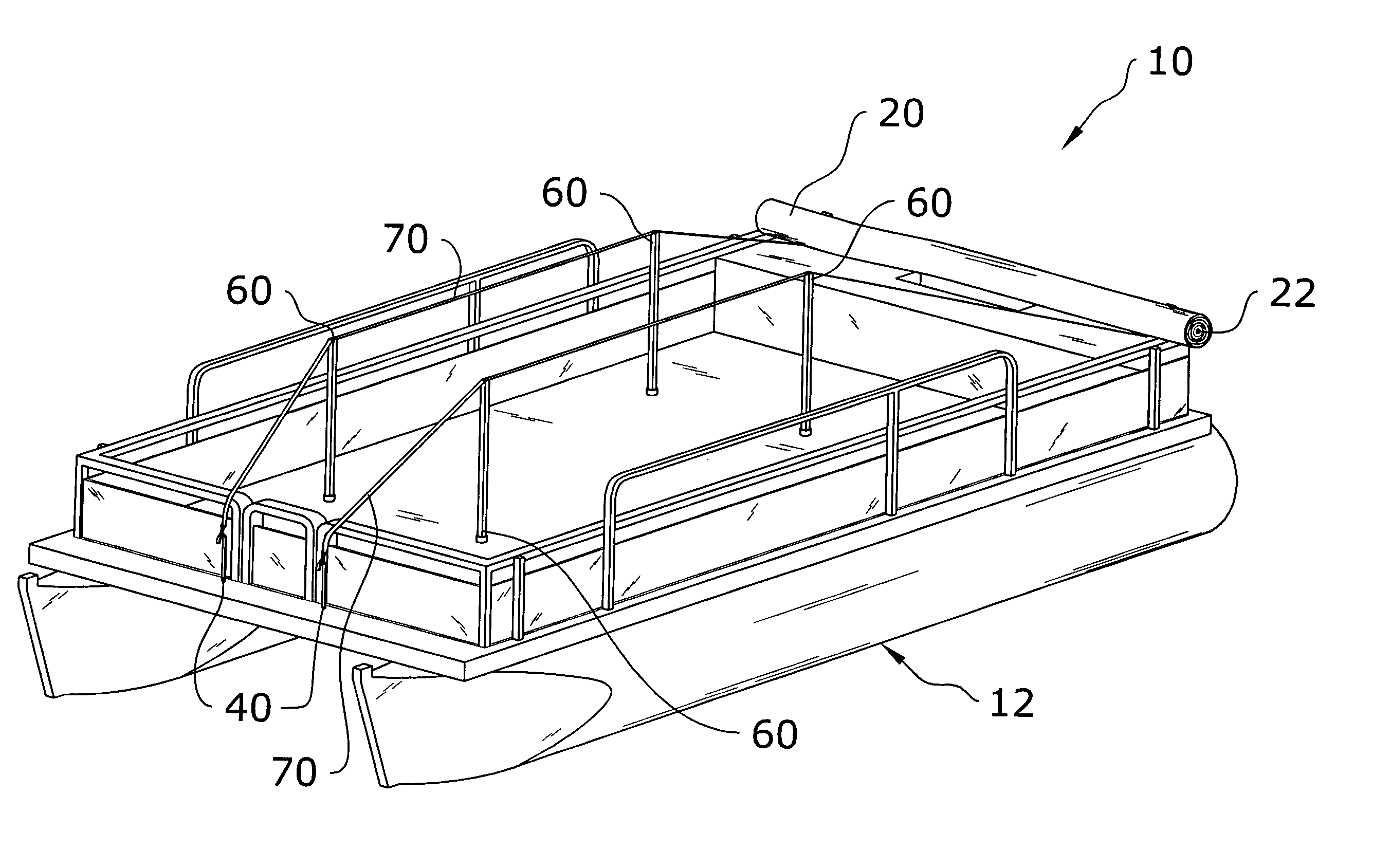
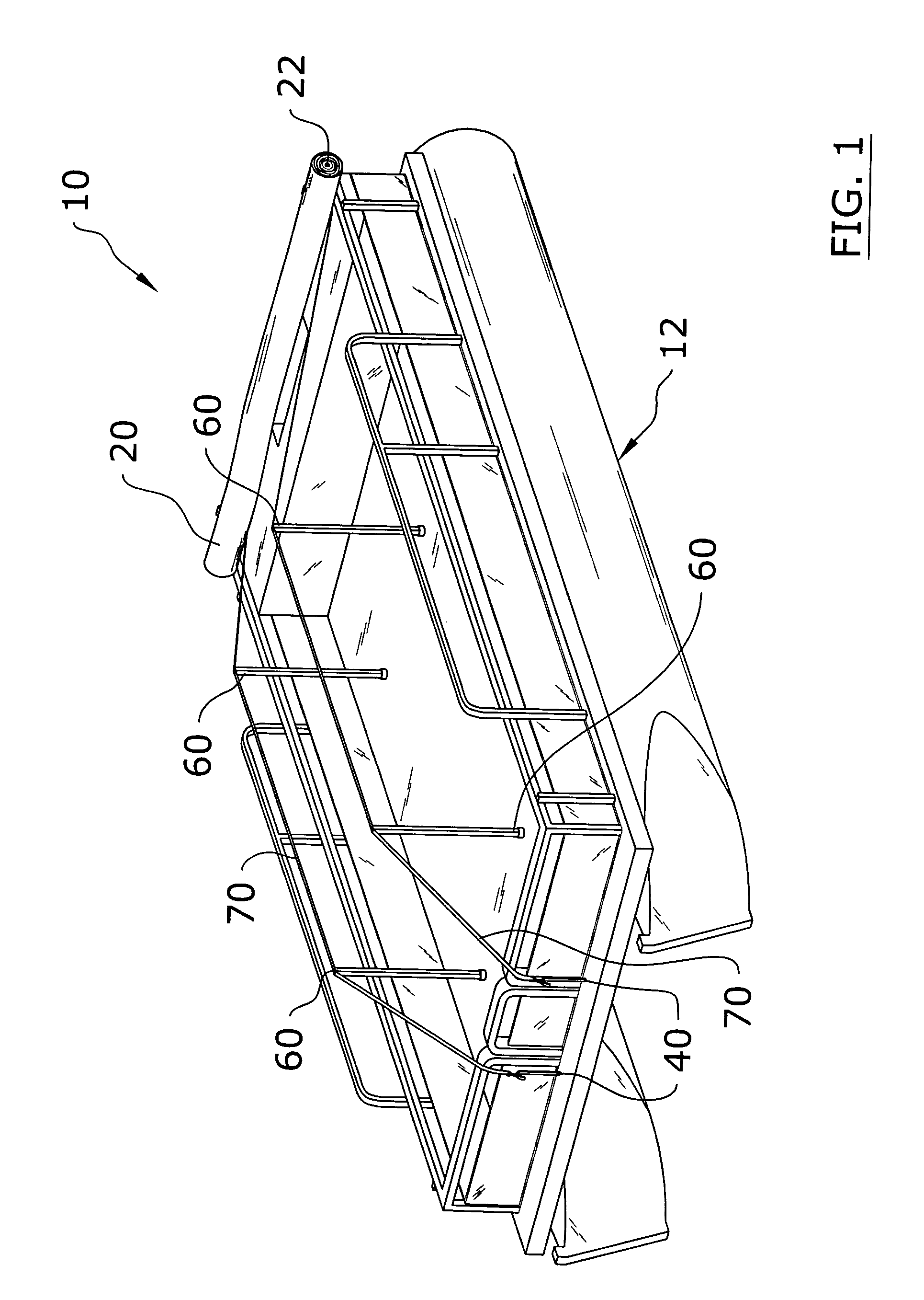
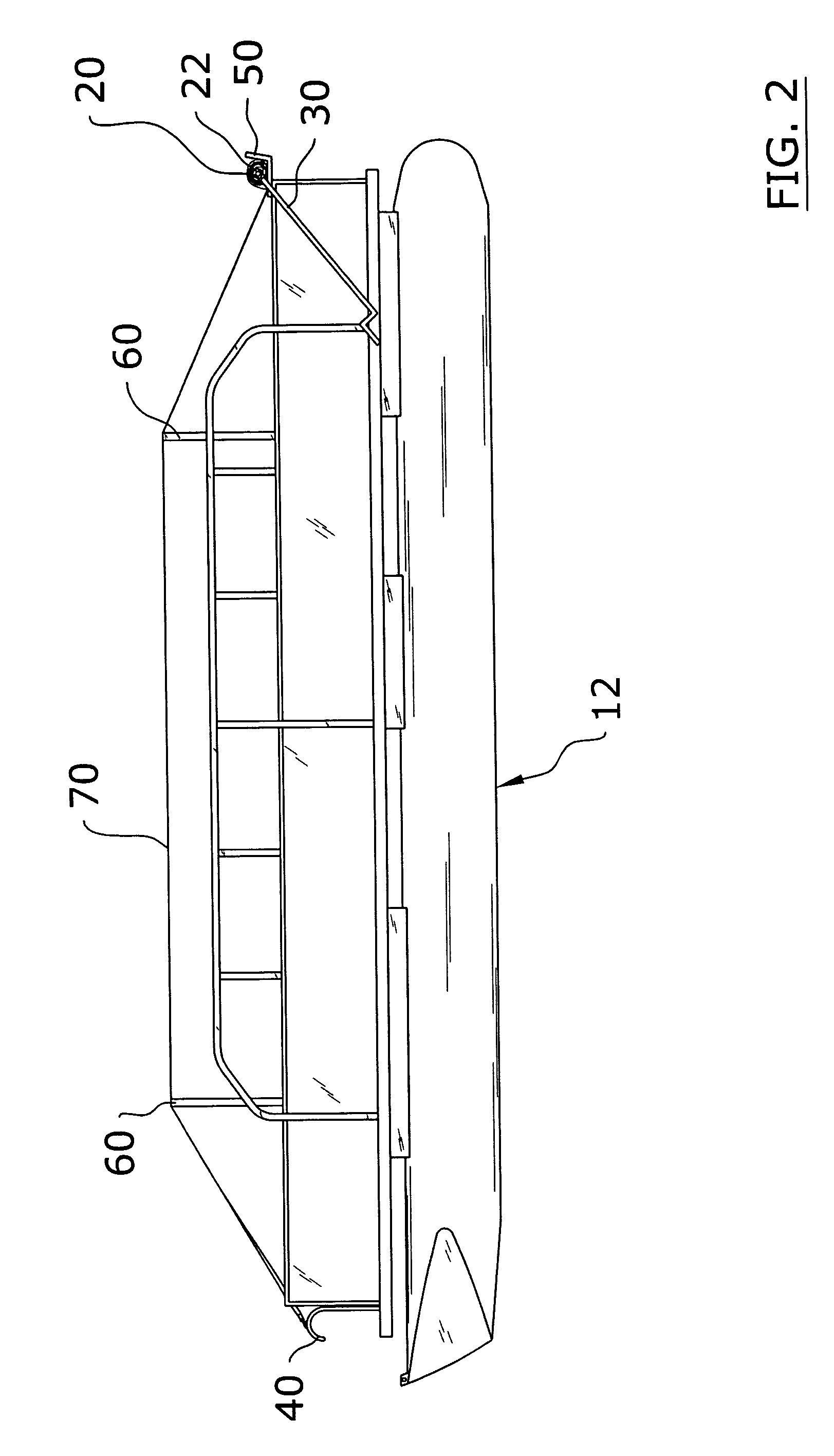
[0032]Turning now descriptively to the drawings, in which similar reference characters denote similar elements throughout the several views, FIGS. 1 through 9 illustrate a pontoon tarpaulin system 10, which comprises a plurality of support poles 60 vertically extendable from a floor of a pontoon 12, a plurality of support bands 70 extending between the ends of the pontoon 12 and slidably attached to an upper end of the support poles 60, and a tarpaulin 20 attached to a core 22 capable of being rolled upon support bands 70. A handle 30 may be attached to the core 22 for allowing the user to roll the tarpaulin 20 from an open position to a closed position (and vice versa). It can be appreciated that a handle 30 is not required to open or close the core 22 if the user manually manipulates the core 22. A plurality of rear supports 50 are attachable to a rear of the pontoon 12 for supporting the tarpaulin 20 when rolled into a storage position. A plurality of front hooks 40 ar...


PUM


Abstract

A pontoon tarpaulin system for efficiently covering a pontoon. The pontoon tarpaulin system includes a plurality of support poles vertically extendable from a floor of a pontoon, a plurality of support bands extending between the ends of the pontoon and attachable to an upper end of the support poles, and a tarpaulin attached to a core capable of being rolled upon support bands. A handle is attachable within the core for allowing the user to roll the tarpaulin from an open position to a closed position. A plurality of rear supports are attachable to a rear of the pontoon for supporting the tarpaulin when rolled into a storage position. A plurality of front hooks are attachable to a front of the pontoon for catchably engaging the core when the tarpaulin is in the closed position.

Description

CROSS REFERENCE TO RELATED APPLICATIONS[0001]Not applicable to this application.STATEMENT REGARDING FEDERALLY SPONSORED RESEARCH OR DEVELOPMENT[0002]Not applicable to this application.BACKGROUND OF THE INVENTION[0003]1. Field of the Invention[0004]The present invention relates generally to pontoon covers and more specifically it relates to a pontoon tarpaulin system for efficiently covering a pontoon.[0005]2. Description of the Related Art[0006]Pontoon covers have been in use for years for protecting pontoons from weather and debris. Conventional pontoon covers are typically comprised of a single size that must be manually positioned over the pontoon. It can be time consuming and labor intensive to position a conventional pontoon cover upon a pontoon. Conventional pontoon covers also typically require 2 or more individuals to secure the cover upon a pontoon.[0007]While these devices may be suitable for the particular purpose to which they address, they are not as suitable for effici...

Claims


Application Information

Patent Timeline
IPC IPC(8): B63B17/00B63B17/02
CPCB63B17/02B63B2017/0054
Inventor JIRAK, JERRY D.
Owner JIRAK JERRY D
Why Eureka
Try Eureka