Bill acceptor with bill passage anti-light pollution arrangement

a bill acceptor and bill passage technology, applied in instruments, sensing record carriers, computing, etc., can solve the problems of false detection or detection errors, unable to filtrate external light rays to eliminate light pollution, and reject valuable papers, etc., to reduce light pollution, reduce the angle of light path, and reduce glare

Inactive Publication Date: 2014-04-01
INT CURRENCY TECH
View PDF10 Cites 11 Cited by
  • Summary
  • Abstract
  • Description
  • Claims
  • Application Information

AI Technical Summary

Benefits of technology

[0011]Further, the holder base of the bill-receiving unit comprises at least one light transmissive portion disposed around the bill passage corresponding to the recognition circuit assembly, a privacy filter locating groove extending around each light transmissive portion, and a dust cover mounted in each privacy filter locating groove to hold one respective privacy filter in each privacy filter locating groove. The privacy filter is made using blind ultra-fine (micro louver) optical technology, and designed to control reflection of light and to reduce glare. The privacy filter decreases the angle of the light path in the bill passage, allowing only the light emitted by the light emitters to pass through the bill passage toward the light sensors. Further, the privacy filter with the respective dust cover can be made in any of a variety of shapes and sizes subject to requirements without affecting the original dust protection function of the dust cover.
[0012]Further, the holder base of the bill-receiving unit comprises at least one light transmissive portion disposed around the bill passage corresponding to the recognition circuit assembly, a privacy filter locating groove extending around each light transmissive portion, and a dust cover mounted in the privacy filter locating groove to hold one respective privacy filter in the at least one light transmissive portion. Further, the control module of the bill-receiving unit comprises two circuit boards respectively mounted in the holder base at opposing top and bottom sides of the bill passage, a plurality of sensors installed in the circuit boards and adapted to sense the insertion of a bill into the bill slot, a bearing shell mounted at each circuit board over the sensors at the respective circuit board. The bearing shell comprises a privacy filter locating groove accommodating at least one privacy filter, and a plurality of retaining protrusions projecting into the privacy filter locating groove to hold at least one privacy filter in the privacy filter locating groove. The privacy filter at the bearing shell filtrates external light rays that are not emitted by the light emitters, reducing light pollution, avoiding errors and faults, and prolonging the lifespan of the bill acceptor.

Problems solved by technology

If a valuable paper is inserted into a bill acceptor in an offset manner, the recognition device of the bill acceptor may reject the valuable paper due to a recognition error.
In this case, the user must insert the valuable paper again, causing inconvenience.
However, during validation operation of a recognition device of a bill acceptor, sunlight or external luminous light or flashing light may pass through the bill slot of the face panel into the internal bill passage of the bill acceptor to fall upon the dust cover and the lens set of the recognition device to interfere with the light being emitted by the light emitter toward the light sensor, resulting in a false detection or detection error.
The dust cover has wear-resistant, dustproof and anti-stain characteristics, but it cannot filtrate external light rays to eliminate light pollution.
When a light pollution occurs, the validation accuracy will be affected.
If an inserted valuable paper cannot be validated and is rejected, the user shall have to insert the valuable paper into the bill slot again, causing inconvenience.

Method used


Image

  • Bill acceptor with bill passage anti-light pollution arrangement
  • Bill acceptor with bill passage anti-light pollution arrangement
  • Bill acceptor with bill passage anti-light pollution arrangement

Examples


Embodiment Construction

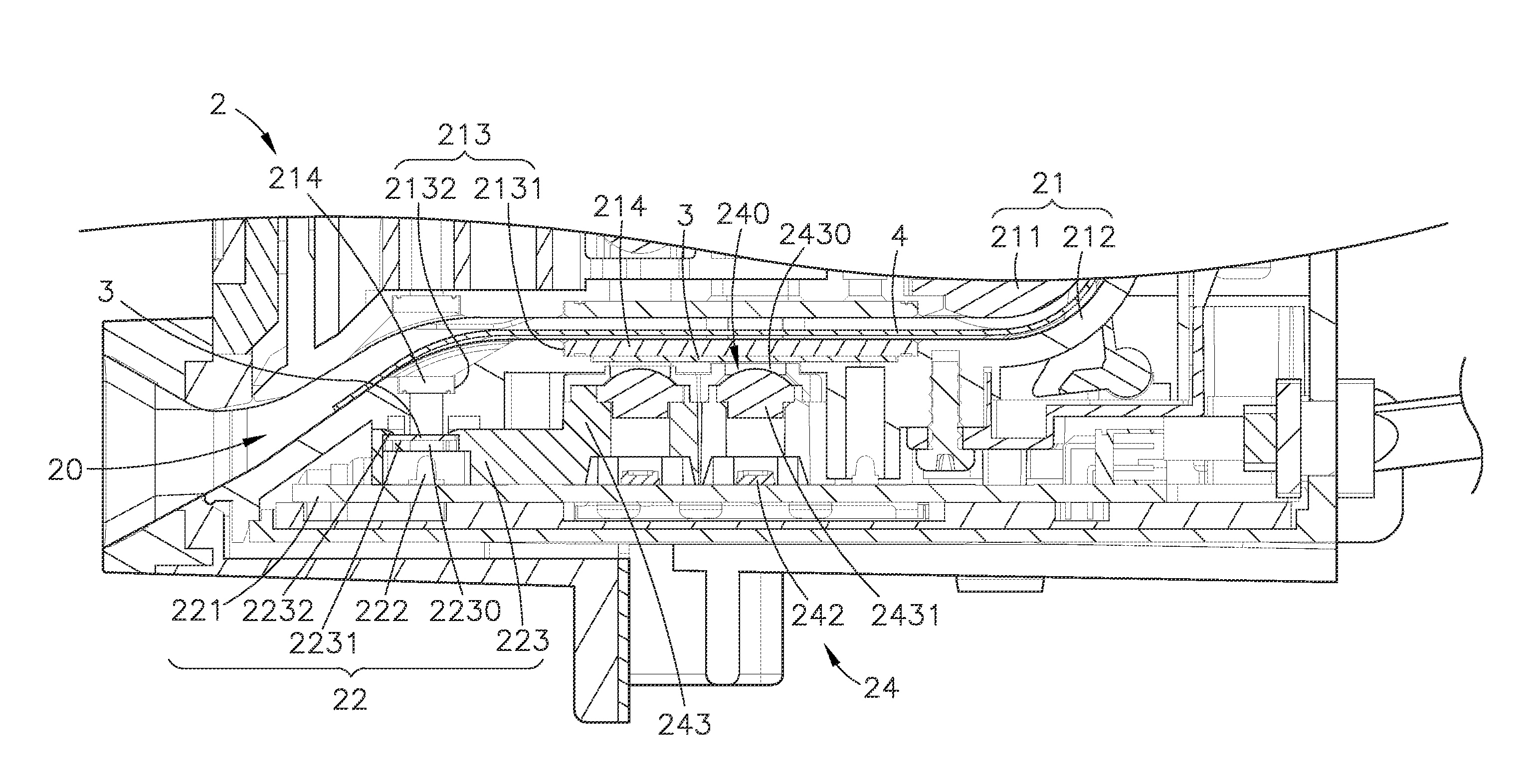
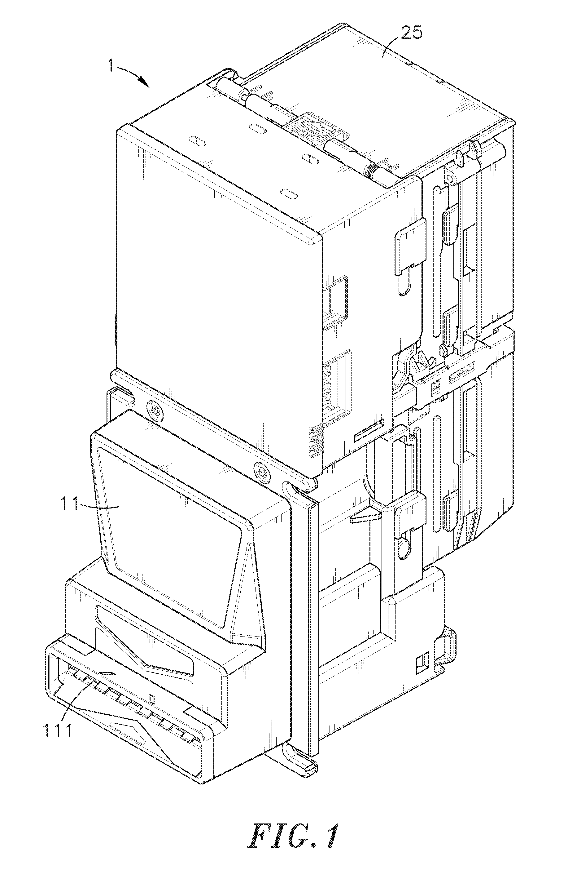
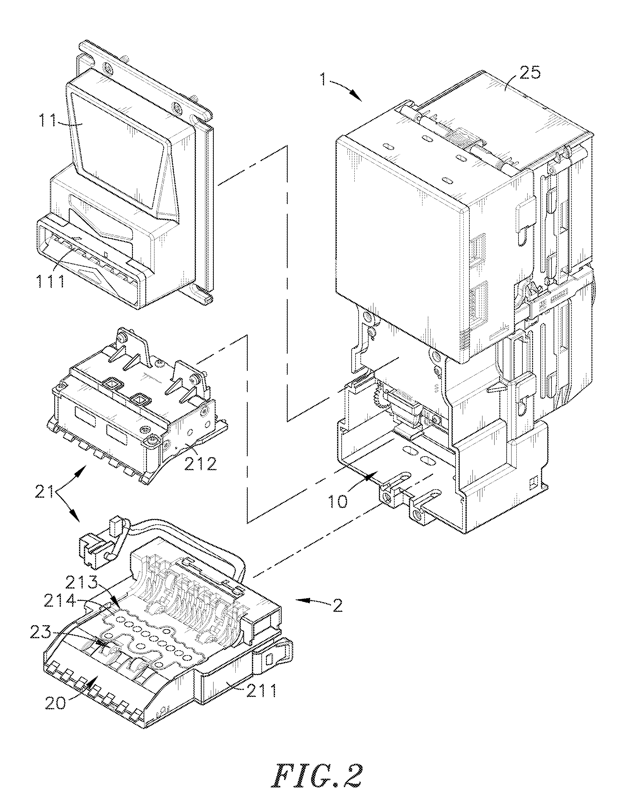
[0019]Referring to FIGS. 1-6, a bill acceptor with bill passage anti-light pollution arrangement in accordance with the present invention is shown comprising a housing 1, and a bill-receiving unit 2. The housing 1 comprises a face panel 11 defining a bill slot 111. Further, the housing 1 defines therein an accommodation chamber 10. The bill-receiving unit 2 is accommodated, in the accommodation chamber 10 of the housing 1, comprising a holder base 21 consisting of a first base member 211 and a second base member 212, a bill passage 20 defined between the first base member 211 and the second base member 212 in communication with the bill slot 111, a control module 22, a transmission mechanism 23 and a recognition circuit assembly 24 mounted in top and bottom sides of the bill passage 20, and a bill box 25 mounted at the rear side of the housing 1. The control module 22 comprises two circuit boards 221 respectively mounted in the top and bottom sides of the bill passage 20 near the bi...


PUM


Abstract

A bill acceptor capable of reducing light pollution, avoiding errors and faults and enhancing detection accuracy and reliability is disclosed to include a housing defining a bill slot in a face panel thereof, a bill-receiving unit accommodated in the housing and including a holder base defining therein a bill passage in communication with the bill slot, a control module, a transmission mechanism and a recognition circuit assembly, the recognition circuit assembly including a sampling and validating module consisting of a plurality of light emitters and light sensors and controllable by the control module to validate the authenticity and face value of an inserted bill, and privacy filters mounted in a light path in the bill-receiving unit between the bill passage and the light sensors to filtrate external light sources and to let the light emitted by the light emitters pass toward the light sensors.

Description

BACKGROUND OF THE INVENTION[0001]1. Field of the Invention[0002]The present invention relates to bill acceptor technology and more particularly, to a bill acceptor with bill passage anti-light pollution arrangement, which has privacy filters installed in the light path of the bill-receiving unit thereof to reduce light pollution, avoiding errors and faults and enhancing detection accuracy and reliability.[0003]2. Description of the Related Art[0004]Following fast development of modern technology, convenience and rapidness have become important demands in our modern daily life. Nowadays, different automatic vending machines, card dispensers, auto teller machines, ticket machines and bill exchange machines are used everywhere to sell different products and / or to provide different services without serviceman. These machines are highly appreciated for the advantage of saving much labor and bringing convenience to people.[0005]Further, commercial automatic vending machines, auto teller m...

Claims


Application Information

Patent Timeline
Patent Type & Authority Patents(United States)
IPC IPC(8): G07F7/04G07D7/00G06K7/00G06K9/00
CPCG07F7/04G06K7/00G06K9/00G07D7/121G07D7/00
Inventor CHANG, CHIA-MIN
Owner INT CURRENCY TECH
Why Eureka
Try Eureka