Apparatus for protecting the knee region of a vehicle occupant

a protection device and vehicle occupant technology, applied in the direction of vehicle components, pedestrian/occupant safety arrangements, vehicular safety arrangments, etc., can solve the problems of affecting the production process, the fastening point of the base chamber and/or the one or more upper chambers can fail, and the volume of the upper chamber cannot be filled too much, so as to achieve convenient fastening and simplify the production process

Active Publication Date: 2014-04-01
AUTOLIV DEV AB
View PDF13 Cites 5 Cited by
  • Summary
  • Abstract
  • Description
  • Claims
  • Application Information

AI Technical Summary

Benefits of technology

[0013]The protection device according to the present invention for vehicle occupants, has a knee airbag which is deployed between the vehicle occupants and a vehicle structure, and a gas generator for filling the knee airbag with inflating gas. The knee airbag has a base chamber which is filled first with inflating gas, and at least one further upper chamber which receives the inflating gas conducted through the base chamber, and wherein a flow obstacle for the inflating gas is arranged between the base chamber and the upper chamber, makes provision for the upper chamber to be rolled up or collapsed and to be secured in the rolled-up or collapsed state, the securing being designed in such a manner that it fails when a predetermined degree of filling of the base chamber is reached. The upper chamber or the upper chambers is or are rolled up or collapsed and is or are fixed in this form so that, during the initial filling of the airbag with inflating gas, the upper chamber or upper chambers do not provide too great a volume which cannot be filled sufficiently rapidly by the gas generator. The securing or fastening of the upper chamber fails when a certain degree of filling of the base chamber is reached, preferably when the base chamber is completely or virtually completely filled. The staggered filling of the individual chambers of the knee airbag make it possible to prevent an uncontrolled movement of the initially unfilled knee airbag elements, i.e. of the one or more upper chambers, in the direction of the occupant or in the direction of the first movement of the airbags after emerging from the casing. A misalignment of the one or more upper chambers can no longer occur, since the lower base chamber, i.e. the chamber which is closest to the gas generator, is filled first and only after the filling thereof, are the subsequent one or more upper chambers filled. With the protection device according to the invention, it is possible to realize a dynamic, curved filling of the airbag without the knee airbag having to be supported upon deployment against the shin bones or knees of a vehicle occupant. This is beneficial in particular to the vehicle occupants who are not in the designated standard position (i.e. an “out of position” occupant).
[0015]The securing, i.e. the catch strap, the tear seam or a different type of securing, will advantageously fail only when the base chamber is completely filled, and therefore a stable base is provided by the completely inflated base chamber such that the lower region of the knee airbag, which region is assigned to the gas generator, ensures reliable positioning of the chambers filled subsequently. By means of the reliable positioning of the upper airbag regions, i.e. of the upper chambers adjoining the base chamber, reliable deployment along the vehicle structure can be ensured.
[0016]The upper chamber is preferably rolled up or collapsed away from the vehicle occupant from the end remote from the gas generator. This means that the knee airbag is rolled up in such a manner that the airbag material is rolled up in the direction of the vehicle structure. Upon deployment, this means that, during the filling of the chambers, a force component acts in the direction of the vehicle structure, since the base chamber and the upper chambers are filled in a wedge-shaped manner, and therefore that region of the chambers which is not yet filled is pressed against the vehicle structure. This assists the desired direction of deployment which is intended to extend along the vehicle structure as close as possible thereto such that optimum deployment can be achieved even without bearing against the lower extremities of the vehicle occupant.
[0020]The securing of the rolled-up regions of the knee airbag, i.e. of the upper chambers, can take place on the lateral edges of the knee airbag, thus enabling the invention to be easily realized without fundamental changes to the operating processes. In this case, the edges of the collapsed upper chambers are fixed, for example adhesively bonded, welded or sewn, to the edges either directly next to the flow obstacle or to the chamber mounted in front in the direction of travel.
[0022]The knee airbag can be collapsed from the end remote from the gas generator in the direction of the gas generator with different folding widths, thus resulting in individual upper chamber layers which are positioned one above another and can be easily fastened to an edge region of the knee airbag or to a tab or a catch strap. In this case, it is provided that the folding width at the end remote from the generator is narrower than that end of the fold which faces the generator, and therefore, at the final fold, there is only a double layer of material or fabric, which layer faces that region of the knee airbag, for example the base chamber, which is mounted upstream in the direction of flow. As a result, only a double layer has to be sewn via a tear seam, which simplifies the production process.

Problems solved by technology

The upper chamber or the upper chambers is or are rolled up or collapsed and is or are fixed in this form so that, during the initial filling of the airbag with inflating gas, the upper chamber or upper chambers do not provide too great a volume which cannot be filled sufficiently rapidly by the gas generator.
After the complete or virtually complete filling of the base chamber, the fastening point on the base chamber and / or the one or more upper chambers can then fail, or, as an alternative thereto, the catch strap can fail.

Method used


Image

  • Apparatus for protecting the knee region of a vehicle occupant
  • Apparatus for protecting the knee region of a vehicle occupant
  • Apparatus for protecting the knee region of a vehicle occupant

Examples


Embodiment Construction

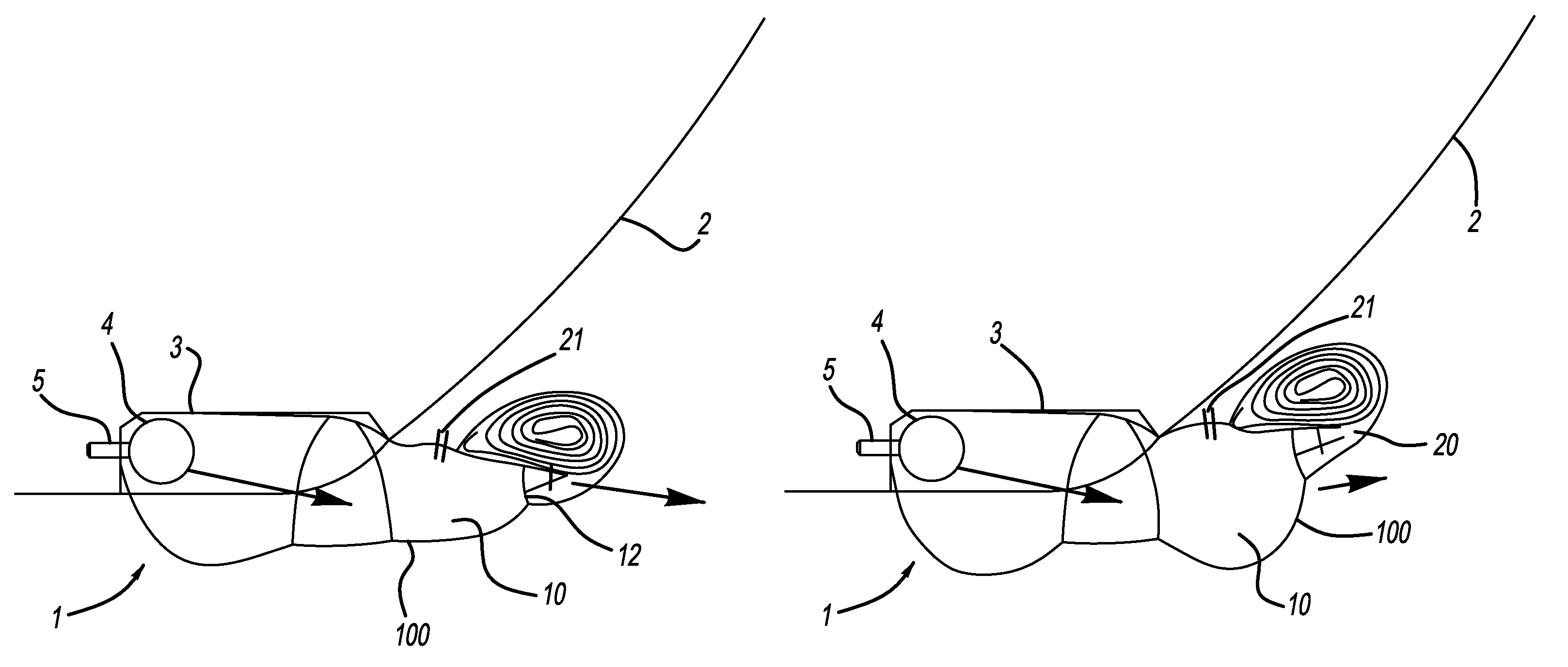
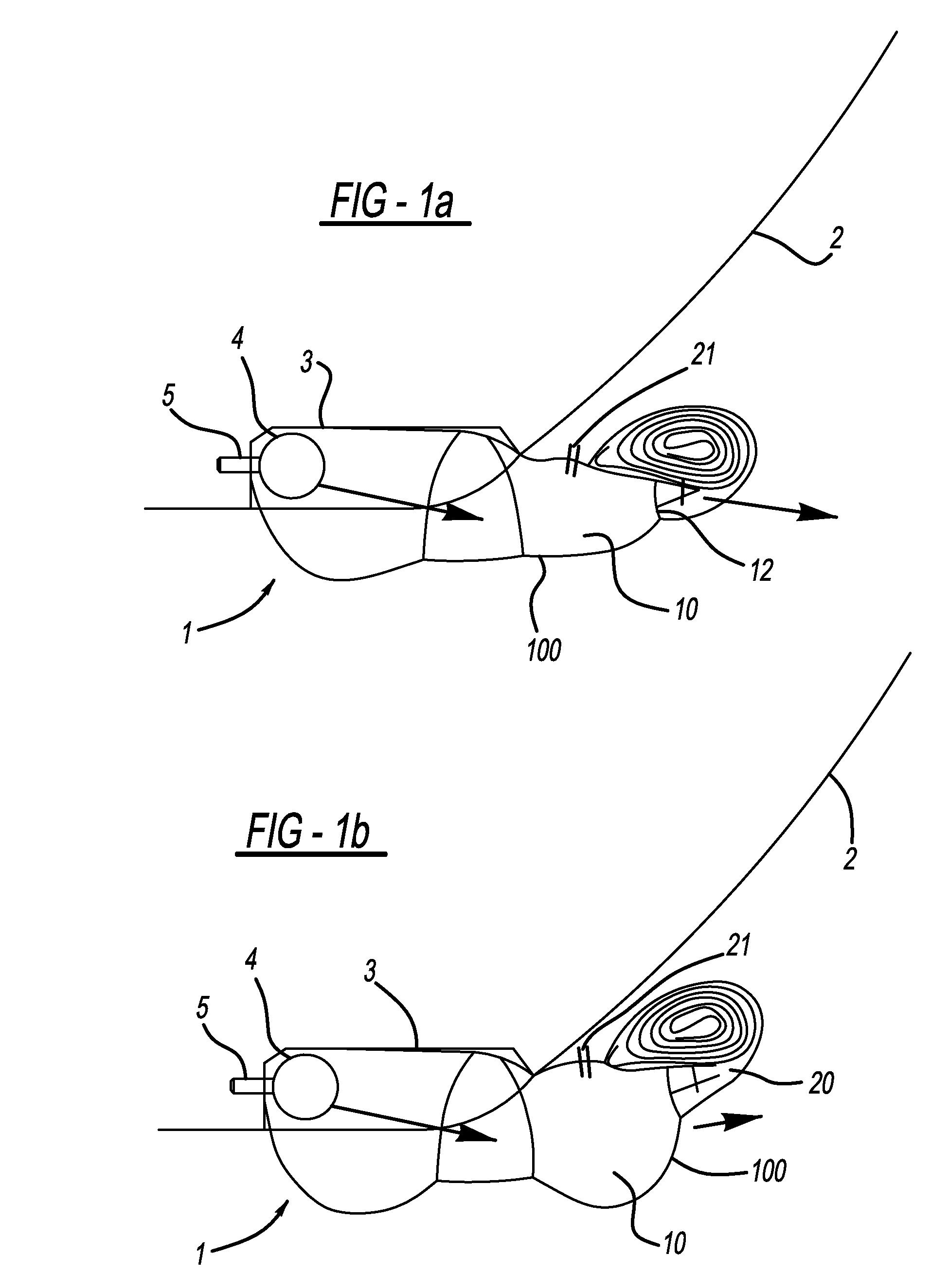
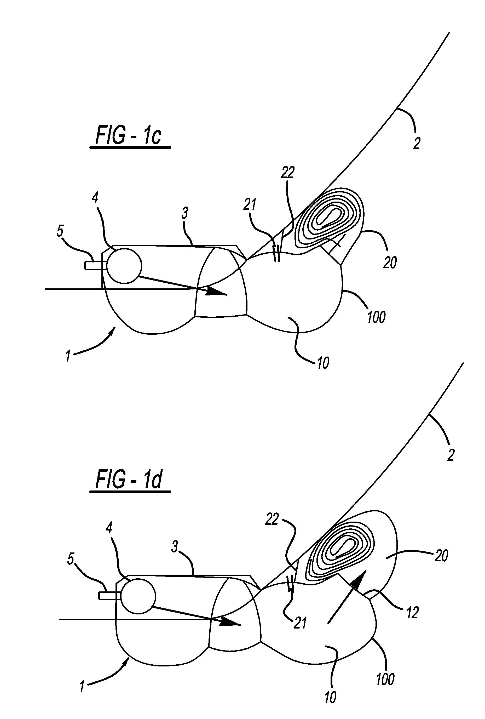
[0026]FIGS. 1a to 1f show a protection device 1 with a knee airbag 100 in various phases of being filled with inflating gas. The protection device 1 is arranged in a vehicle structure 2, for example an instrument panel of a motor vehicle. A module housing 3 in which a gas generator 4 is fixed via fastening bolts 5 is formed or arranged in the vehicle structure 2. The knee airbag 100 is also accommodated within the module housing 3 and concealed in a collapsed state behind a covering (not shown). In the rest position, the knee airbag 100 is completely collapsed or folded up. After detection of an accident or of an imminent accident, the gas generator 4 is activated and inflating gas is introduced into the knee airbag 100, as indicated by the arrow. FIG. 1a illustrates the ejection of the knee airbag 100 out of the module housing 3. The knee airbag 100 together with the module housing 3 and the gas generator 4 is arranged in the lower region of the vehicle structure 2, i.e. in the foo...


PUM


Abstract

A knee airbag (100) which is deployed between the vehicle occupants and a vehicle structure (2) and a gas generator (4) for filling the knee airbag (100) with inflating gas, wherein the knee airbag (100) has a base chamber (10) which is filled first with inflating gas, and at least one further upper chamber (20, 30) which receives the inflating gas conducted through the base chamber (10). A flow obstacle (12, 23) for the inflating gas is arranged between the base chamber (10) and the one or more upper chambers (20, 30). The one or more upper chambers (20, 30) is rolled up or collapsed and is secured in the rolled-up or collapsed state, the securing (21, 22) being designed in such a manner that it fails when a predetermined degree of filling of the base chamber (10) is reached.

Description

CROSS-REFERENCE TO RELATED APPLICATIONS[0001]This application claims priority to German Patent Application No. 10 2009 050 384.6, filed Oct. 22, 2009 and PCT / EP2010 / 005473, filed Sep. 7, 2010.FIELD OF THE INVENTION[0002]The invention relates to an impact protection device for motor vehicle occupants, with a knee airbag which is deployed between the vehicle occupants and a vehicle structure, and a gas generator for filling the knee airbag with inflating gas, wherein the knee airbag has a base chamber which is filled first with inflating gas, and at least one further upper chamber which receives the inflating gas conducted through the base chamber, and wherein a flow obstacle for the inflating gas is arranged between the base chamber and the upper chamber.BACKGROUND OF THE INVENTION[0003]A protection device of above mentioned general type is, in particular, preferably used for knee airbags which have a low-lying installation position such that, during inflation, the knee airbag has to...

Claims


Application Information

Patent Timeline
Patent Type & Authority Patents(United States)
IPC IPC(8): B60R21/206B60R21/201B60R21/2342B60R21/233
CPCB60R2021/161B60R21/2338B60R2021/23388B60R2021/23169B60R2021/23324B60R2021/23308
Inventor PICARD, GREGORREITER, THOMASBERGER, INGO
Owner AUTOLIV DEV AB
Why Eureka
Try Eureka