
Apparatus for removing and/or placing a workpiece from or in an injection mold of an injection molding machine

a technology of injection molding machine and workpiece, which is applied in the direction of dough shaping, manufacturing tools, drawing profiling tools, etc., can solve the problems of unfavorable toothed rack disengagement, etc., and achieve the effect of reliable operation conditions and beneficial effects

Inactive Publication Date: 2006-03-14
KRAUSS MAFFEI KUMSTSTOFFTECHNIK GMBH
View PDF6 Cites 0 Cited by
  • Summary
  • Abstract
  • Description
  • Claims
  • Application Information

AI Technical Summary

Benefits of technology

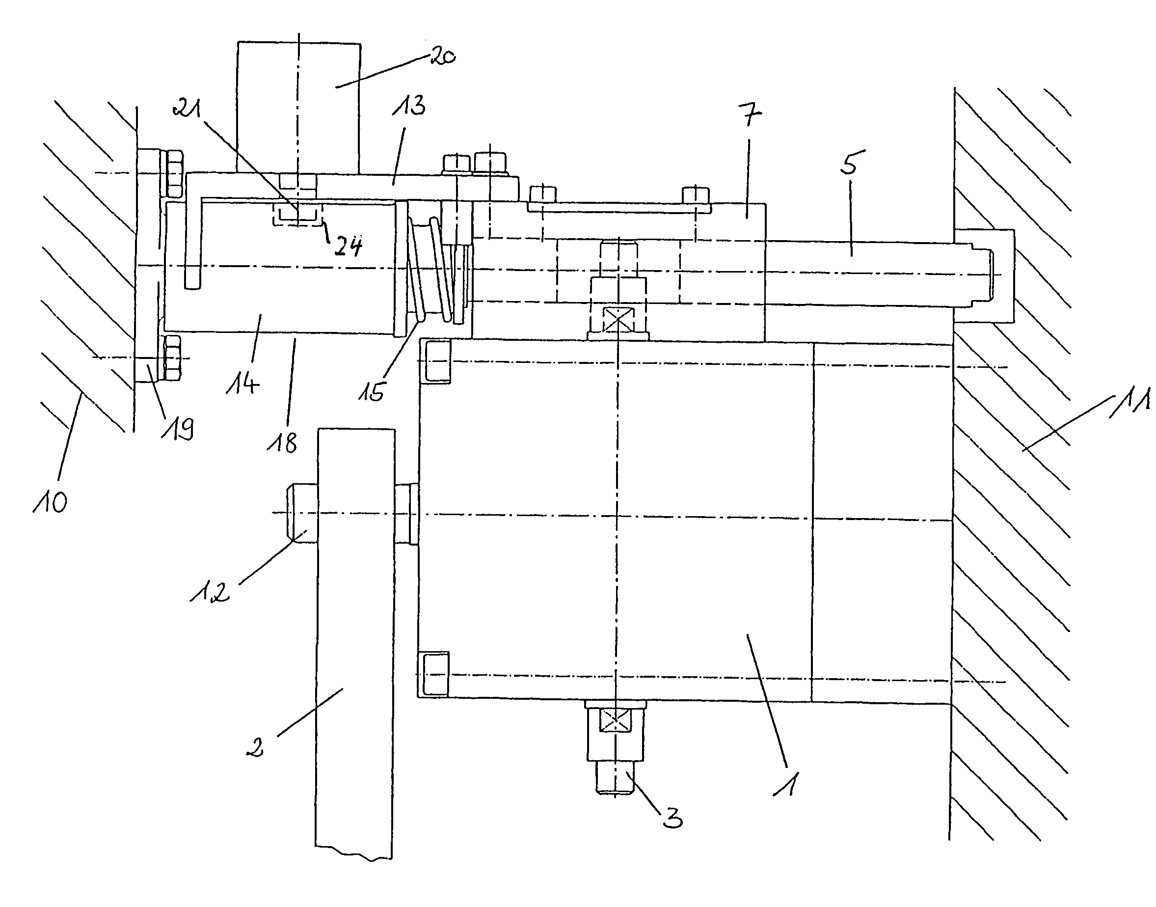
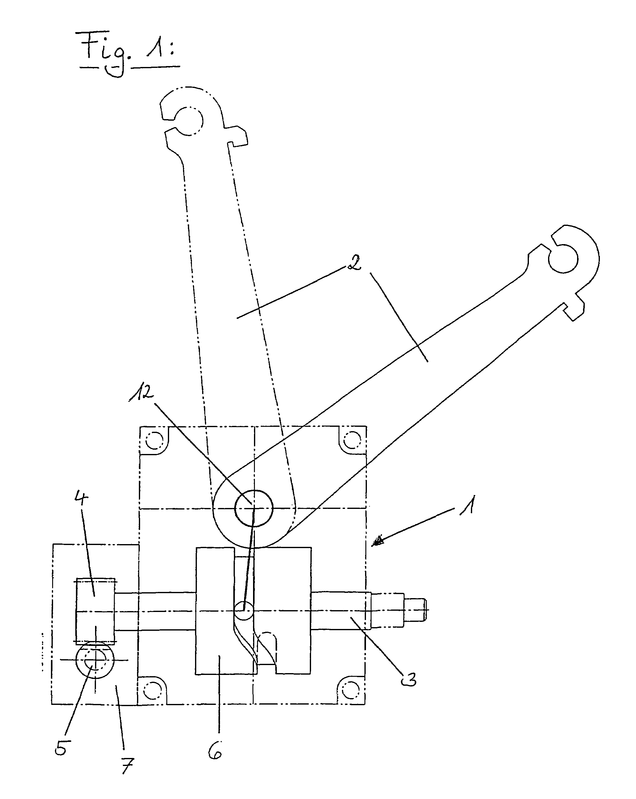
[0010]The use of a globoid cam gear affords also the possibility to predefine so-called dead centers of the output shaft of the cam gear, whereby the output shaft is stationary in the dead centers, even though the input shaft may continue to run. Thus, in accordance with the present invention, the swinging movement of the gripper arm is initiated only after moving a short initial opening stroke, to assure a sufficient distance from all machine components, even when swinging back with the workpiece. In addition, the gripper arm reaches the gripping position already at a point of the opening stroke which is located ahead of the end position of the opening stroke. Thus, a further opening of the mold to assume the end position does no longer influence the position of the gripper arm in view of the configuration of the globoid cam gear. As a consequence, a greater tolerance for the end position of the opening stroke is established.
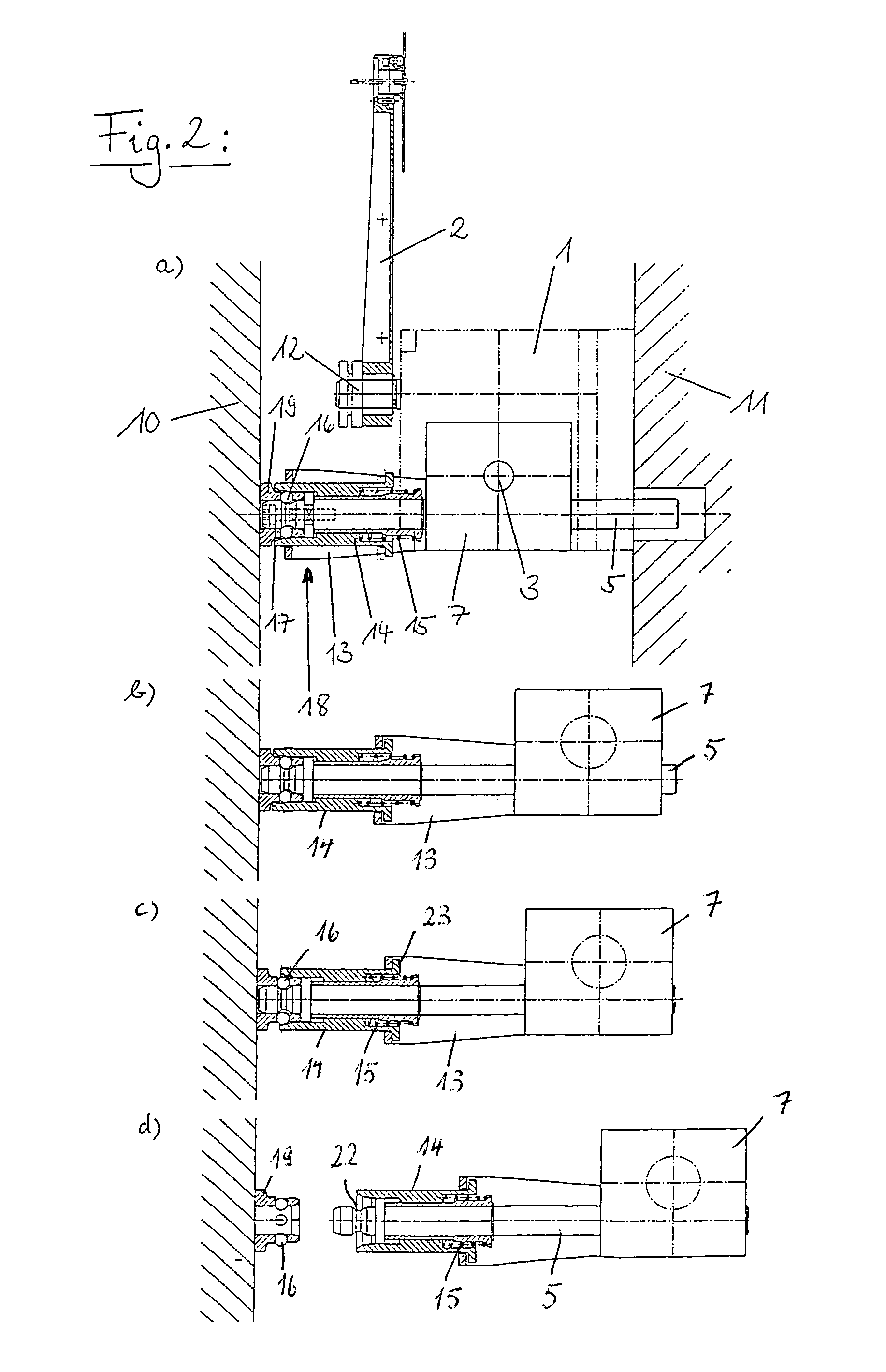
[0012]The coupling for connecting the fixed platen and the toothed rack can be released as soon as the moving platen travels beyond the end position of the opening stroke. In this way, the predefined end point of the globoid curve cannot be overrun. In addition, an uncontrolled and unintended movement of the gripper arm beyond the gripping position can thus be prevented, which would take pace when overrunning the end position and is dependent on the configuration of the globoid curve.
[0014]The toothed rack is so supported on the globoid cam gear as to be borne by a fork which is securely fixed to the globoid cam gear. The fork engages a mechanical release mechanism on the side of the toothed rack for disengaging the coupling and is so constructed as to activate the release mechanism, when the travel of the fork exceeds a predetermined distance. The fork is hereby also configured to allow easy and reliable re-engagement of the toothed rack, when the platens move back into a closing position and following an overrun of the end position of the opening stroke, whereby the globoid cam gear automatically assumes the correct end position. As a result, there is no need to precisely fit the toothed rack into a bearing assembly upon the globoid cam gear, and there is no longer any need to re-adjust the precise position of the globoid cam gear in relationship to the opening stroke of the injection mold, as required to date.
[0018]The present invention thus provides an apparatus for removing and / or placing a workpiece from or in an injection mold of an injection molding machine, which apparatus displays especially beneficial and reliable operating conditions.

Problems solved by technology

This type of extraction unit suffers shortcomings because the toothed rack continues to operate the globoid cam gear, when the mold opens beyond a preset stroke during normal operation, so that the swingable lever assumes an undesired position.
In the event, the mold opens even further, there is the risk of disengagement of the toothed rack from the spur gear that is seated on the output shaft of the globoid cam gear and detachment of the bearing of the toothed rack upon the cam gear.
Excessive opening strokes of platens are oftentimes caused during operation of an injection molding machine because the control of the clamping mechanism may become defective, or because necessary maintenance works or mold exchange needs to be done.

Method used


Image

  • Apparatus for removing and/or placing a workpiece from or in an injection mold of an injection molding machine
  • Apparatus for removing and/or placing a workpiece from or in an injection mold of an injection molding machine
  • Apparatus for removing and/or placing a workpiece from or in an injection mold of an injection molding machine

Examples


Embodiment Construction

[0023]Throughout all the Figures, same or corresponding elements are generally indicated by same reference numerals. These depicted embodiments are to be understood as illustrative of the invention and not as limiting in any way. It should also be understood that the drawings are not necessarily to scale and that the embodiments are sometimes illustrated by graphic symbols, phantom lines, diagrammatic representations and fragmentary views. In certain instances, details which are not necessary for an understanding of the present invention or which render other details difficult to perceive may have been omitted.

[0024]Turning now to the drawing, and in particular to FIG. 1, there is shown a sectional view of a globoid cam gear, generally designated by reference numeral 1 and provided for a novel and inventive apparatus for removing and / or placing a workpiece from or in an injection mold of an injection molding machine. The globoid cam gear 1 includes a globoid cam roller 6 with an inp...


PUM

PropertyMeasurementUnit
distanceaaaaaaaaaa
mechanicalaaaaaaaaaa
forceaaaaaaaaaa

Abstract

Apparatus for removing and / or placing a workpiece from or into an injection mold of an injection molding machine includes a fixed platen and a moving platen which have attached thereon respective half-molds. A toothed rack is firmly connected to the fixed platen and engages with a drive pinion of a globoid cam gear which is disposed on the moving platen or attached half-mold and has an output shaft for attachment of a gripper arm. To prevent the gripper arm from moving into an undesired position, when the injection mold is opened beyond a predefined distance, the toothed rack and the fixed platen are connected through the intervention of a detachable coupling, whereby a release mechanism is provided to disengage the coupling when a distance between the fixed and moving platens exceeds a predetermined value.

Description

CROSS-REFERENCES TO RELATED APPLICATIONS[0001]This application is a continuation of prior filed copending PCT International application No. PCT / EP02 / 08740, filed Aug. 6, 2002, which designated the United States and on which priority is claimed under 35 U.S.C. §120, the disclosure of which is hereby incorporated by reference.[0002]This application claims the priority of German Patent Application, Serial No. 101 52 936.8, filed Oct. 26, 2001, pursuant to 35 U.S.C. 119(a)–(d), the disclosure of which is incorporated herein by reference.BACKGROUND OF THE INVENTION[0003]The present invention relates to an apparatus for removing and / or placing a workpiece from or in an injection mold of an injection molding machine, in particular injection molding machine for processing plastics.[0004]Injection-molded articles have to be removed cyclically from the open injection molding machine, before a next injection-molding step can begin. German patent publication no. DE 199 39 228 describes an extra...

Claims


Application Information

Patent Timeline
Patent Type & Authority Patents(United States)
IPC IPC(8): B29C31/08B29C45/42
CPCB29C45/4208
Inventor GEISSLER, ANTONMENK, MICHAEL
Owner KRAUSS MAFFEI KUMSTSTOFFTECHNIK GMBH
Learn More