Piezoelectric microblower

a micro-blower and piezoelectric technology, applied in the direction of positive displacement liquid engine, piston pump, pump parameter, etc., can solve the problems of significant heat generation inside compact electronic devices, such as notebook computers and digital av devices, displacement is significantly reduced, flow rate is reduced, etc., to achieve good blower performance and increase the flow rate

Active Publication Date: 2014-04-01
MURATA MFG CO LTD
View PDF25 Cites 40 Cited by
  • Summary
  • Abstract
  • Description
  • Claims
  • Application Information

AI Technical Summary

Benefits of technology

[0009]To overcome the problems described above, preferred embodiments of the present invention provide a piezoelectric microblower that can be of reduced size while still obtaining good blower characteristics.

Problems solved by technology

The generation of heat inside compact electronic devices, such as notebook computers and digital AV devices, for example, is a significant problem.
In this kind of piezoelectric microblower, there has been a problem in that if the size of the vibrating plate is reduced so as to reduce the size of the blower, the displacement is significantly reduced, whereby the flow rate is reduced and the desired cooling effect cannot be obtained.
Therefore, it has not been possible to sufficiently reduce the size of such blowers.
Where the characteristic frequency of the vibrating plate inside the casing satisfies the conditions for Helmholtz resonance in the casing, the noise is increased.
However, if the resonant frequency of the casing is 1.09 kHz and the cavity volume is 1.5×10⁻⁵ m3, for example, the casing has approximate dimensions of 100 mm×30 mm×5 mm and cannot be used for very compact mobile appliances.
Furthermore, at a driving frequency of 1 kHz, since it is within the audible range, noise becomes a problem.
However, first-order resonant frequencies may be within the audible range and, thus, noise is a problem.
However, if the diameter of the diaphragm is reduced to attempt to reduce the size of the blower, since the displacement is significantly reduced, the characteristics of the blower are deteriorated and the desired cooling effect is not obtained.

Method used


Image

  • Piezoelectric microblower
  • Piezoelectric microblower
  • Piezoelectric microblower

Examples


first preferred embodiment

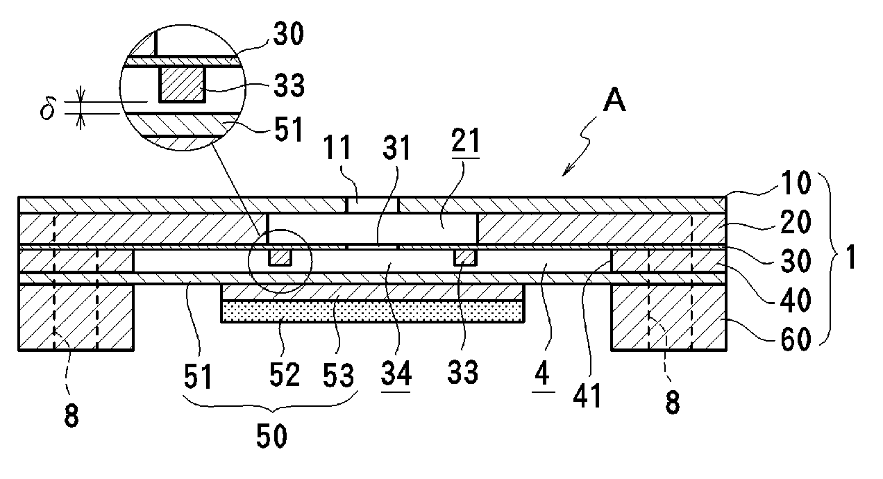
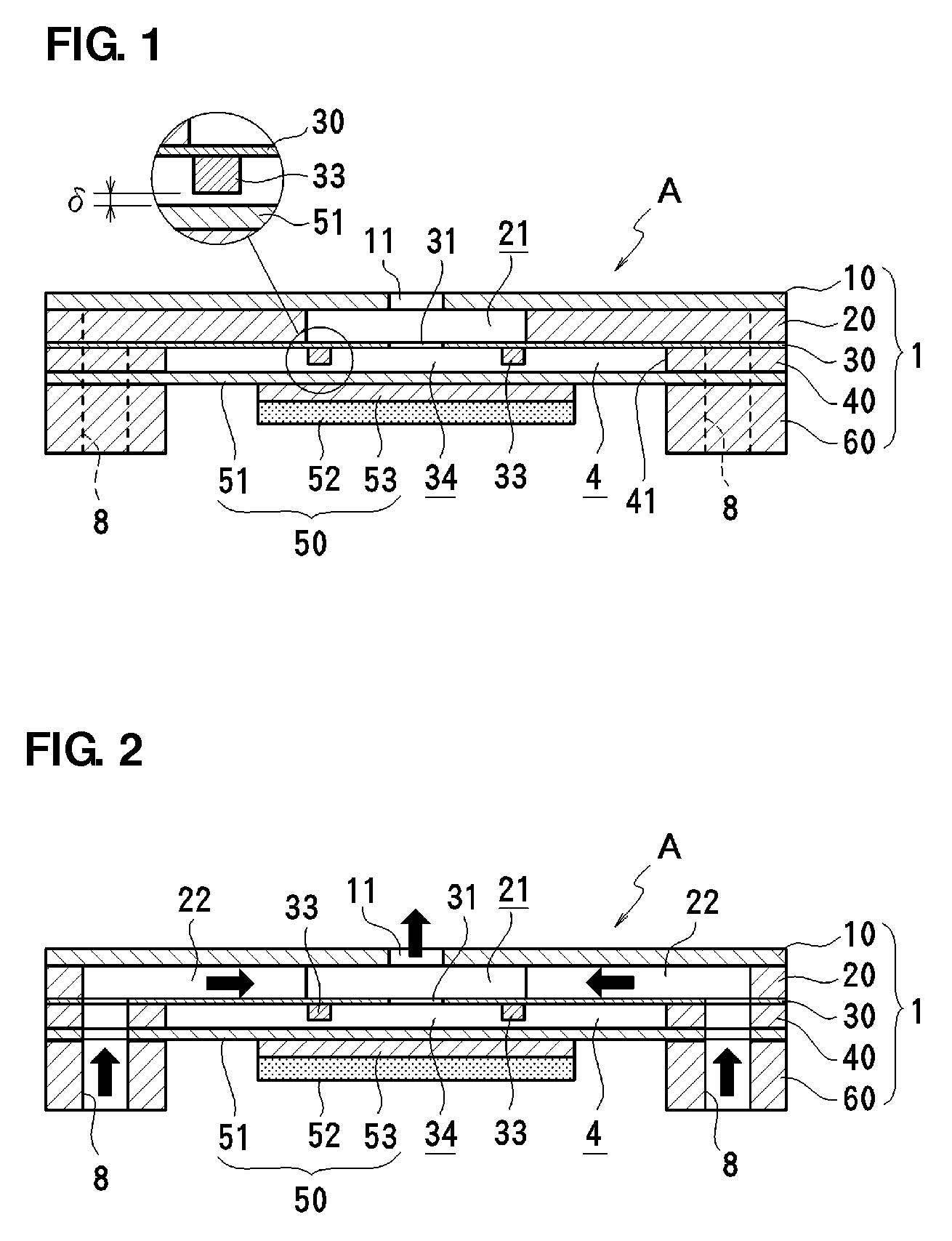
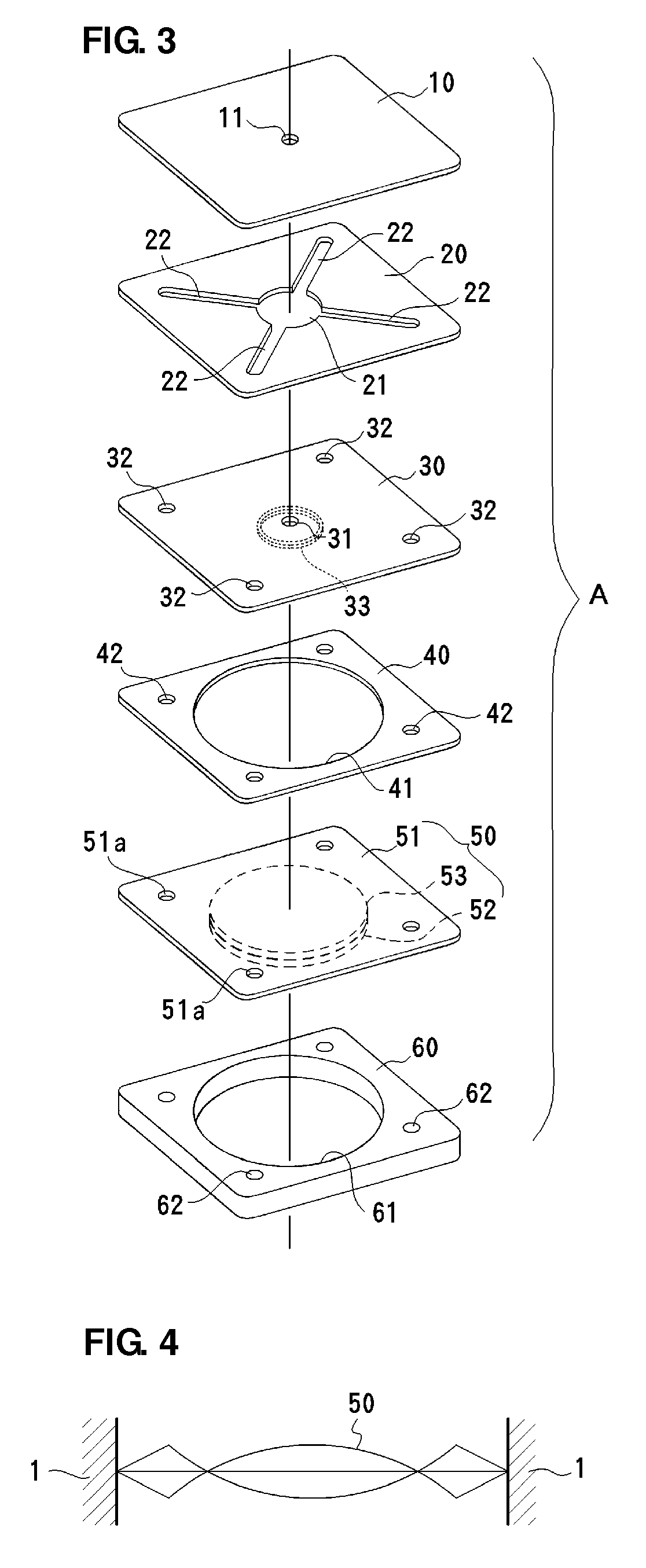
[0037]A piezoelectric microblower according to a first preferred embodiment of the present invention is illustrated in FIGS. 1 to 3. In this preferred embodiment, an example will be described in which a vibrating plate 50 is resonantly driven. A piezoelectric microblower A according to this preferred embodiment is an example of a microblower preferably used as an air-cooling blower of an electronic appliance and includes a top plate (second wall) 10, a flow-passage-forming plate 20, a separator (first wall) 30, a blower frame 40, the vibrating plate 50, and a bottom plate 60 that are stacked on top of one another in order from top to bottom and attached to one another. The outer periphery of a diaphragm 51 of the vibrating plate 50 is preferably bonded between the blower frame 40 and the bottom plate 60. The top plate 10, the flow-passage-forming plate 20, the separator 30, the blower frame 40, and the bottom plate 60 define a blower body 1 and preferably include rigid flat-plate-sh...

second preferred embodiment

[0048]FIG. 5 illustrates a piezoelectric microblower according to a second preferred embodiment of the present invention. The structure of a microblower B of this preferred embodiment preferably is substantially the same as that of the piezoelectric microblower A of the first preferred embodiment, except that a ring-shaped piezoelectric element 52a is preferably attached to the upper surface of the diaphragm 51 with a ring-shaped intermediate plate 53a therebetween to define a vibrating plate 50a, and therefore, the same reference numerals are used and redundant description is omitted.

[0049]In this preferred embodiment, when the vibrating plate 50a is resonantly driven in the third-order mode, the diaphragm 51 deforms as illustrated in FIG. 6. That is, the displacement of the central portion of the diaphragm 51 is very large as compared to that at the peripheral portion. In this case, the central portion of the diaphragm 51 at which the displacement is greatest defines the resonant ...

third preferred embodiment

[0052]FIG. 8 illustrates a piezoelectric microblower according to a third preferred embodiment of the present invention. A microblower C of this preferred embodiment is substantially the same as the piezoelectric microblower A of the first preferred embodiment, except that the partition 33 is preferably fixedly attached to the top surface of the diaphragm 51. In this preferred embodiment, the partition 33 also vibrates up and down with the resonant driving of the vibrating plate 50, and therefore, it is necessary to provide a predetermined gap δ between the partition 33 and the separator 30 facing the top thereof. Provided that the location of the partition 33 is set to be in the vicinity of a node point of the vibrating plate 50, vibration of the partition 33 is reduces, which is preferable.


PUM


Abstract

A piezoelectric microblower includes a vibrating plate including a piezoelectric element and arranged to be driven in a bending mode by applying a voltage of a predetermined frequency to the piezoelectric element, and a blower body arranged to fix both ends or a periphery of the vibrating plate and to define a blower chamber between the blower body and the vibrating plate, an opening being provided in a portion of the blower body facing a central portion of the vibrating plate. In a portion of the blower chamber corresponding to the central portion of the vibrating plate, a partition is provided around the opening and a resonance space is defined inside of the partition. A size of the resonance space is set such that a driving frequency of the vibrating plate and a Helmholtz resonance frequency of the resonance space correspond to each other.

Description

BACKGROUND OF THE INVENTION[0001]1. Field of the Invention[0002]The present invention relates to piezoelectric microblowers used to transport a compressible fluid, such as air.[0003]2. Description of the Related Art[0004]The generation of heat inside compact electronic devices, such as notebook computers and digital AV devices, for example, is a significant problem. It is important and necessary that cooling blowers used in such devices are compact, have a low profile, and have low power consumption.[0005]Driving units that are used in cooling blowers include a diaphragm that is bent and deformed by a piezoelectric member. Generally, a vibrating plate is provided as a diaphragm that is made of a thin resin or metal plate to which a piezoelectric element is attached. Advantageously, this structure has a low profile and low power consumption. Airflow is generated by applying an alternating voltage to the piezoelectric element so as to cause bending deformation, whereby the pressure in...

Claims


Application Information

Patent Timeline
Patent Type & Authority Patents(United States)
IPC IPC(8): F04B35/04F04B17/00
CPCF04B45/047F04B2201/12F04B2201/0806
Inventor KANAI, SHUNGOKAMITANI, GAKUKANEDA, YOKO
Owner MURATA MFG CO LTD
Why Eureka
Try Eureka