Method for controlling brushless DC motor

a brushless dc motor and motor control technology, applied in the direction of motor/generator/converter stopper, electronic commutator, dynamo-electric converter control, etc., can solve the problems of increasing power consumption, high phase current of coil winding of the motor, etc., and achieve the effect of saving power and reducing cos

Active Publication Date: 2014-04-01
ZHONGSHAN BROAD OCEAN
View PDF6 Cites 25 Cited by
  • Summary
  • Abstract
  • Description
  • Claims
  • Application Information

AI Technical Summary

Benefits of technology

[0006]In view of the above-described problem, it is one objective of the invention to provide a method for controlling a brushless DC motor that enables the motor to operate at the minimum phase current, saves power, reduces cost and improves working efficiency.
[0022]Advantages of the invention comprise: as the motor enters a stable state, the motor advances or delays phase shift at the optimum offset angle αm, at this time operating current of a coil winding of the motor is the minimum, which saves power and reduces cost.

Problems solved by technology

However, there is a problem with the motor: due to position errors of the Hall sensor or low accuracy of electronic components of the measuring unit, a measured phase shift position of the rotor is not an appropriate position, which causes phase current of coil windings of the motor to be very high, and increases power consumption.

Method used


Image

  • Method for controlling brushless DC motor
  • Method for controlling brushless DC motor
  • Method for controlling brushless DC motor

Examples


example 1

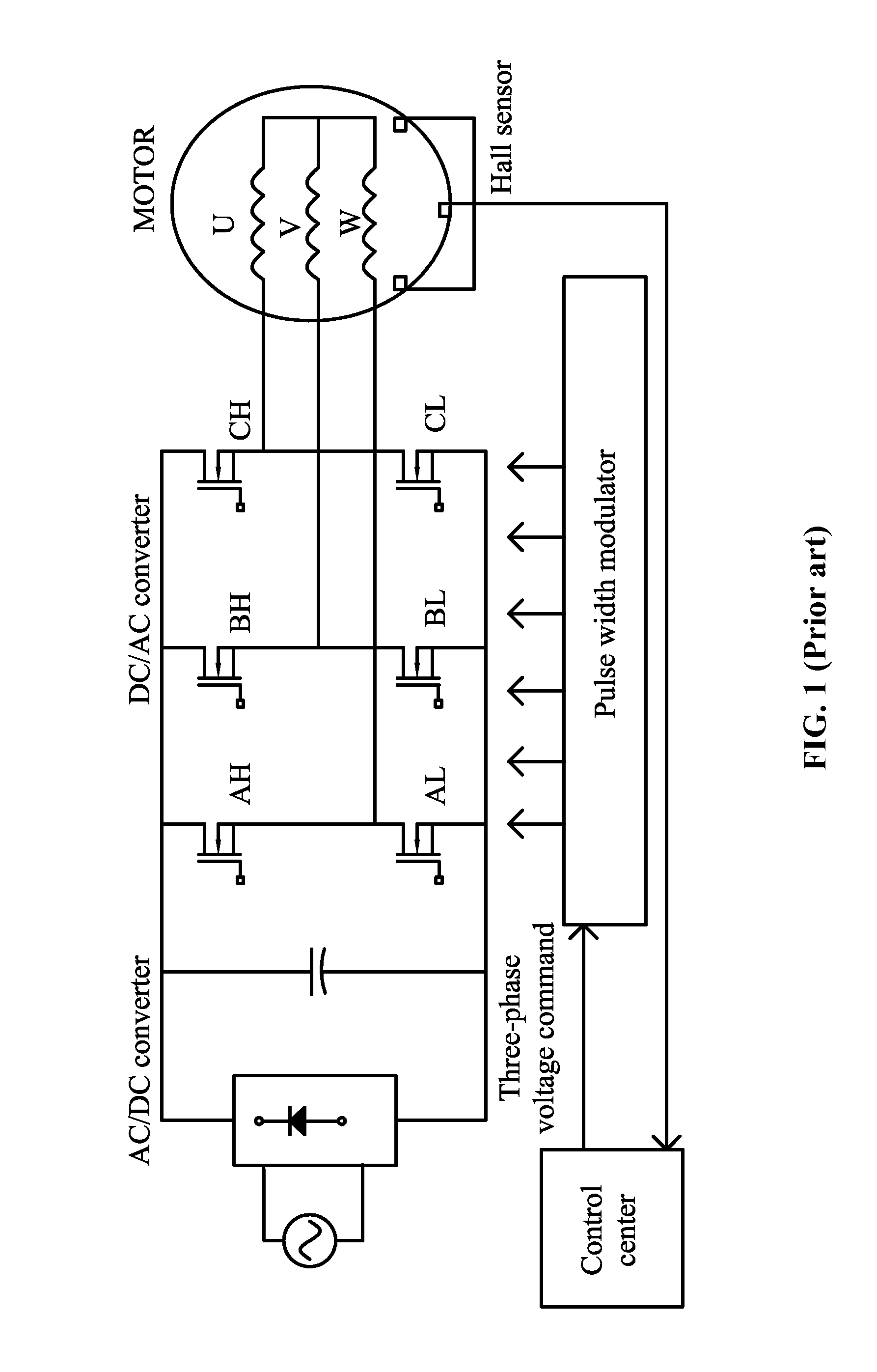
[0036]As shown in FIG. 3, after six phase shift moments T1, T2, . . . , T6, a phase shift period is formed. As the rotor of the motor rotates a circle, transistors AH and BL are connected to coil windings W and V, transistors AH and CL are connected to coil windings W and U, transistors BH and CL are connected to coil windings V and U, transistors BH and AL are connected to coil windings V and W, transistors CH and AL are connected to coil windings U and W, and transistors CH and BL are connected to coil windings U and V.

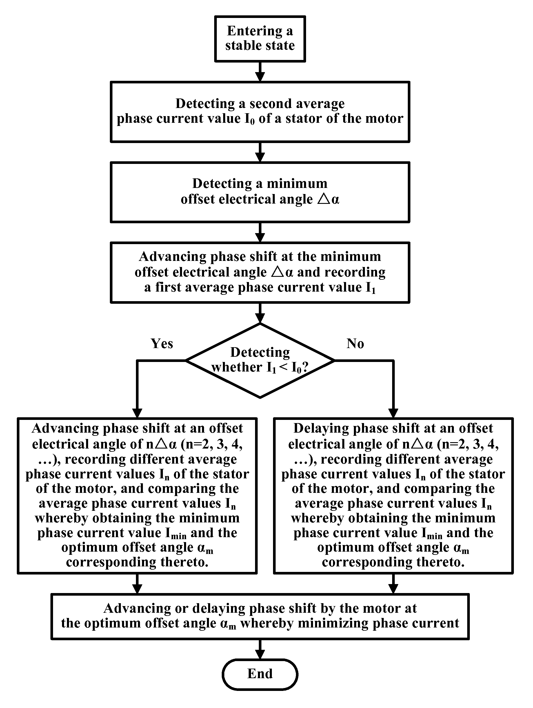
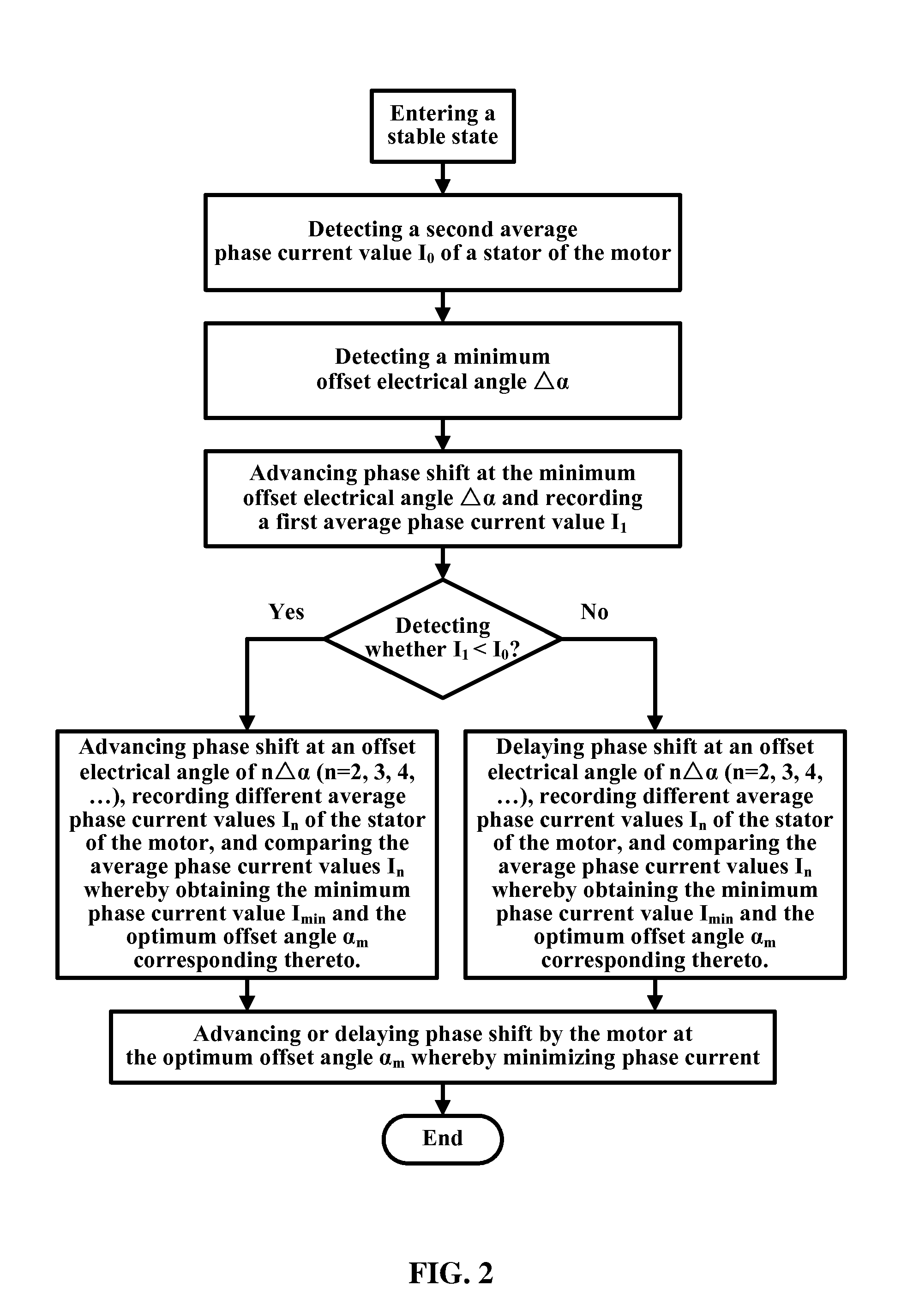
[0037]In principle, phase shift is performed once every 60 degrees. However, due to position errors of the Hall sensor or low accuracy of electronic components of a measuring unit, a phase shift position of the rotor is not the optimum phase shift position, which causes large operating current of all coil windings and increases power consumption. Therefore, as the motor enters the stable state (for example, it rotates at a constant speed of 1000 circles per minute),...

example 2

[0046]As shown in FIG. 5, the single-phase brushless DC motor requires no phase shift, but current commutation. Flow of current in one direction can be implemented via transistors Q1 and Q4, and the flow of current in the other direction can be implemented via transistors Q2 and Q3. In principle, phase shift is performed once every 180 degrees. However, due to position errors of the Hall sensor or low accuracy of electronic components of a measuring unit, a phase shift position of the rotor is not the optimum phase shift position, which causes large operating current of all coil windings and increases power consumption. Therefore, as the motor enters the stable state (for example, it rotates at a constant speed of 1000 circles per minute), an optimum phase shift position needs to be obtained whereby minimizing the phase current value.

[0047]As a Hall sensor transmits a signal at a time, the transistors Q1 and Q4 are enabled, and the coil windings are also enabled and operate.

[0048]A ...


PUM


Abstract

A method for controlling a brushless DC motor, comprising transmitting a phase-inversion signal to a motor control unit by a rotor position detecting unit after a motor enters a stable state, advancing or delaying phase shift by the motor control unit at an offset electrical angle, recording and comparing phase current values In at different offset electrical angles whereby obtaining an optimum offset angle αm corresponding to the minimum phase current value Imin, and advancing or delaying phase shift by the motor at the optimum offset angle αm. As the motor enters a stable state, the motor advances or delays phase shift at the optimum offset angle αm, at this time operating current of a coil winding of the motor is the minimum, which saves power and reduces cost.

Description

CROSS-REFERENCE TO RELATED APPLICATIONS[0001]Pursuant to 35 U.S.C. §119 and the Paris Convention Treaty, this application claims the benefit of Chinese Patent Application No. 200910038187.3 filed on Mar. 20, 2009, the contents of which are incorporated herein by reference.BACKGROUND OF THE INVENTION[0002]1. Field of the Invention[0003]The invention relates to a method for controlling a motor, and more particularly to a method for controlling a brushless DC motor.[0004]2. Description of the Related Art[0005]As shown in FIG. 1, a conventional brushless DC motor in the prior art comprises a controller, an AC / DC converter, a DC / AC converter, a hall sensor, and a pulse width modulator (PWM). Phase shift of the conventional motor is implemented by detecting a position of a rotor via a measuring unit, and the measuring unit may be a Hall sensor. However, there is a problem with the motor: due to position errors of the Hall sensor or low accuracy of electronic components of the measuring un...

Claims


Application Information

Patent Timeline
Patent Type & Authority Patents(United States)
IPC IPC(8): H02K29/00H02P23/00
CPCH02P6/145H02P6/16H02P6/153
Inventor BI, RONGHUAZHAO, YONG
Owner ZHONGSHAN BROAD OCEAN
Why Eureka
Try Eureka