On-base enclosure

a technology of enclosure and base, applied in the field of enclosure, can solve the problems of not providing sufficient acoustical attenuation of the sound generated by the equipment, adding considerable time to open or remove the enclosure for inspection or maintenance, and little room around the perimeter of the equipment to maneuver

Inactive Publication Date: 2014-04-08
GENERAL ELECTRIC CO
View PDF20 Cites 28 Cited by
  • Summary
  • Abstract
  • Description
  • Claims
  • Application Information

AI Technical Summary

Benefits of technology

[0006]Generally stated, the present invention provides an enclosure for equipment mounted on a base. The enclosure has a plurality of outer walls attached to the base; a chamber formed by the outer walls, wherein the chamber is sized to hold said equipment. The chamber has a horizontal cross-sectional surface area. The base has a horizontal base area and a perimeter edge. At least one of the outer walls is attached to the base such that the at least one outer wall is extended a distance outward from the perimeter edge of the base. This provides a chamber having a cross-sectional surface area, which is greater than the surface area of the base. The enclosure provides more room within the enclosure to access the equipment mounted on the base.

Problems solved by technology

Disadvantages of on-base enclosures include there is little room around the perimeter of the equipment to maneuver around the equipment for inspection or to access the equipment, for example for maintenance.
This adds considerable time to open or remove these panels for inspection or maintenance.
Also, these panels, due to their removable or movable nature, generally do not provide sufficient acoustical attenuation of sound generated by the equipment.
However, off-base enclosures typically need a separate foundation to support the walls and roof of the enclosure.
This results in increased installation time, the need to build an additional foundation and, in the case of fire extinguishing agent, a larger amount is generally needed for an off-base enclosure.
Further, off-base enclosures are often built with more space than necessary around the equipment.

Method used


Image

  • On-base enclosure
  • On-base enclosure
  • On-base enclosure

Examples


Embodiment Construction

[0016]To gain a better understanding of the invention, attention is directed to the Figures of the present specification.

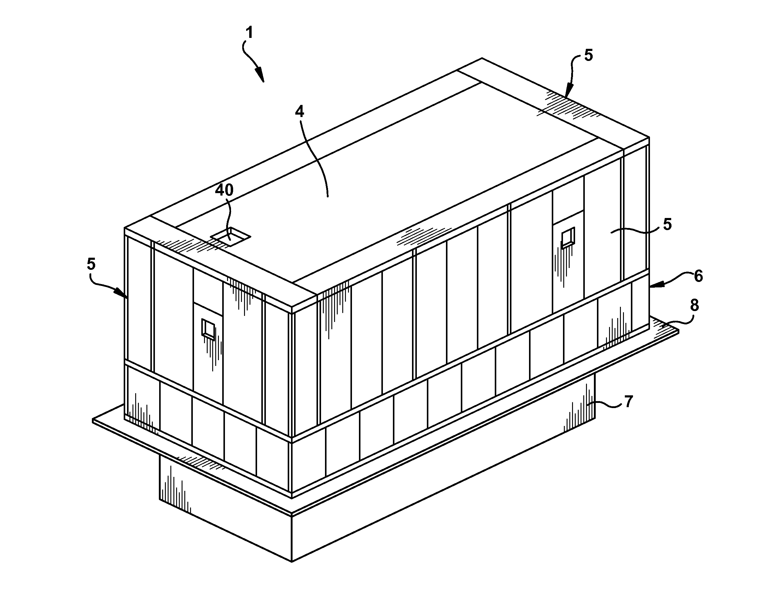
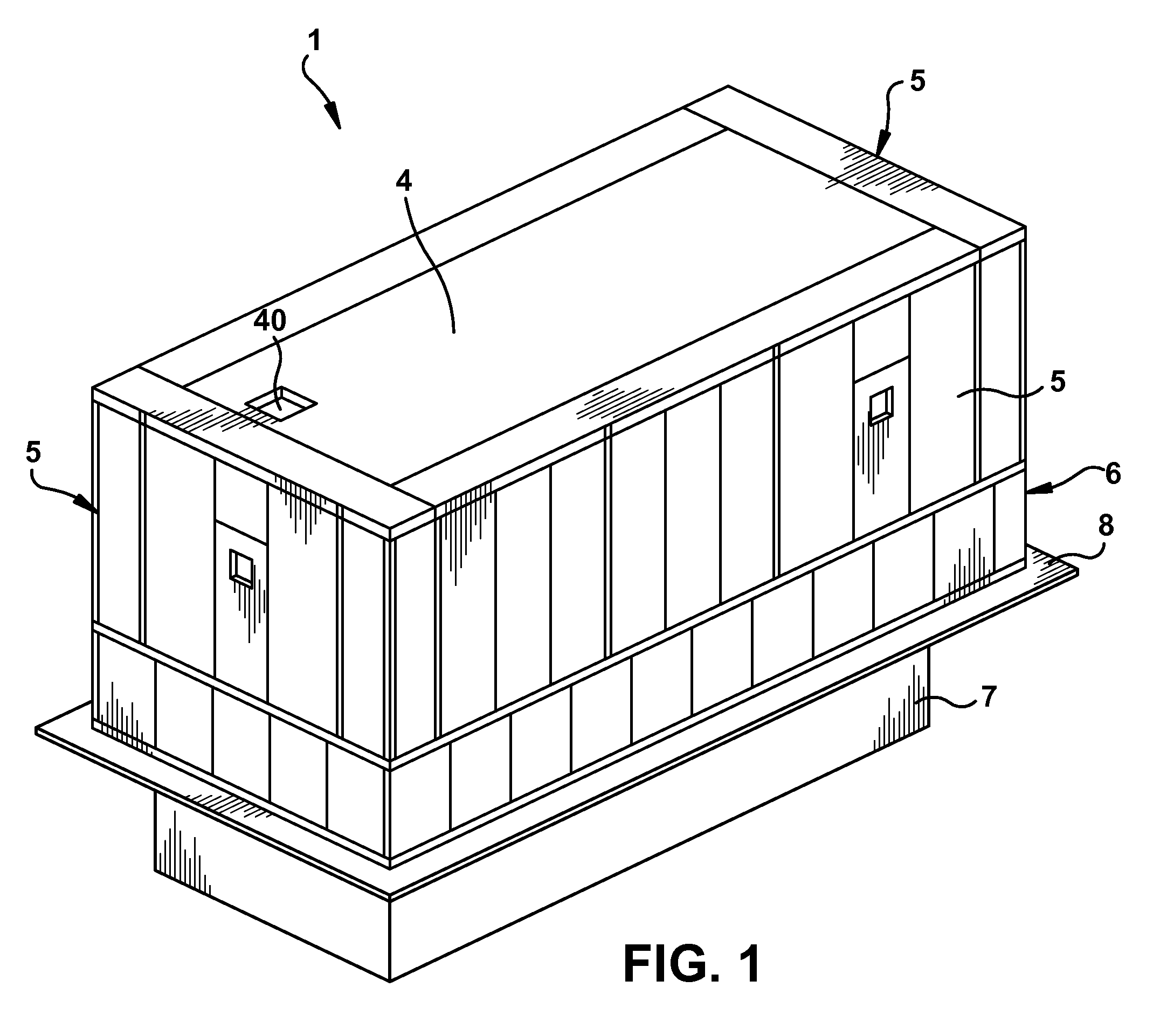
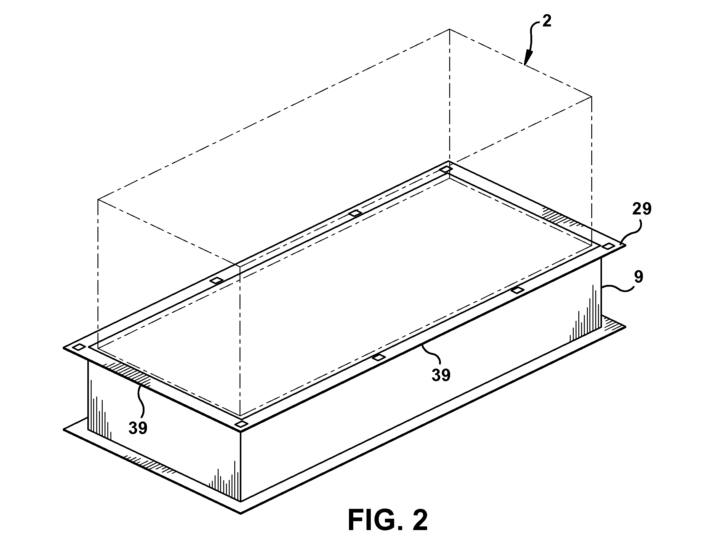
[0017]Referring to FIGS. 1 and 2, shown is enclosure 1 on base 9. Equipment 2 (shown only as a general volume phantom box) is supported by and mounted to base 9. Base 9 has an upper surface 29 with perimeter edge 39 extending around base upper surface 29. Upper surface 29 may extend out from base 9, as shown in FIG. 2, or may be flush with base 9 (not shown). Upper surface 29 is part of the base 9. Attached to base 9 is a plurality of outer walls 5. Outer walls 5 form chamber 3, shown in FIG. 4, which surrounds and encloses equipment 2. Chamber 3 is an interior room formed by enclosure 1. Enclosure 1 may further have upper wall or roof 4, which serves to enclose equipment 2 within chamber 3. Chamber 3 has an interior volume, which is defined by inner surfaces of outer walls 5, upper surface 29 of base 9 and an inner surface of roof 4. This interior volume of chamb...


PUM

PropertyMeasurementUnit
perimeteraaaaaaaaaa
distanceaaaaaaaaaa
areaaaaaaaaaaa

Abstract

An on-base enclosure for equipment is disclosed. The on-base enclosure has walls attached to a base for equipment such that the walls are attached to the base at a distance away from the base. By providing the walls away from the base, more room is provided around the equipment within the enclosure.

Description

FIELD OF THE INVENTION[0001]The invention generally relates to an enclosure mounted on a base, where the base supports a piece of equipment.BACKGROUND OF THE INVENTION[0002]Large pieces of equipment or modules of equipment located at plants or other locations are often enclosed in structures for various reasons, including protecting the equipment from the outside environment, including heat, cold, dust, humidity, and precipitation; providing acoustical attenuation of noise generated by the equipment; and to protect individuals and other machinery in the vicinity of the equipment in the case of an equipment malfunction. Currently, there are two types of enclosures that are generally used. The first type of enclosure is an on-base enclosure, where walls of the enclosure are attached to the base holding the equipment in place. Another type of enclosure is an off-base enclosure, where walls of the enclosure are supported by a separate or independent support structure, other than the bas...

Claims


Application Information

Patent Timeline
Patent Type & Authority Patents(United States)
IPC IPC(8): E04H1/00G10K11/04H02K5/24B64F1/26F02B77/13
CPCF02C7/24F16M7/00B05B15/12F16M1/00Y10T29/49826
Inventor DUPONT, DENIS
Owner GENERAL ELECTRIC CO
Why Eureka
Try Eureka