
Collapsible safety rail system

a safety rail and collapsible technology, applied in the field of safety rail systems, can solve the problems of insufficient realization of the attributes of such an active system, the difficulty of secure and waterproof installation of the horizontal lifeline, and the cost and time-consuming of the fall prevention system, so as to reduce the viewable profile

Inactive Publication Date: 2014-04-08
TRACTEL INC
View PDF30 Cites 18 Cited by
  • Summary
  • Abstract
  • Description
  • Claims
  • Application Information

AI Technical Summary

Benefits of technology

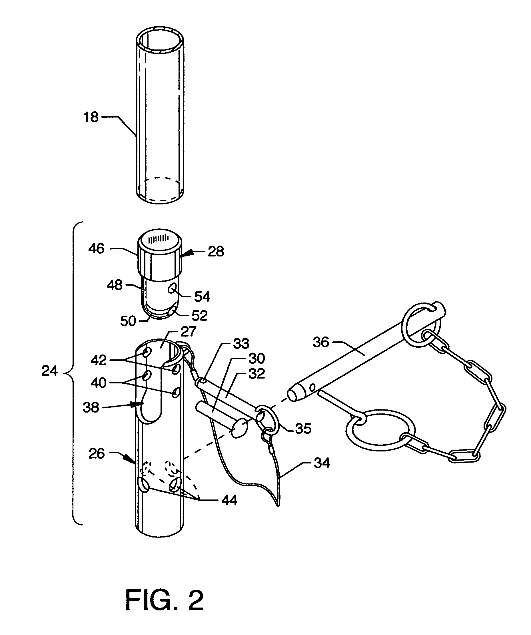
[0006]The general purpose of the present invention is to provide a collapsible safety rail system which is portable and which is intended to be used to provide for fall protection from elevated or other work areas where human safety is an issue. The collapsible safety rail system is a portable system which can be broken down to a plurality of individual collapsible safety rail assemblies and a plurality of heavy and substantial cast iron bases which support the collapsible safety rail assemblies. The collapsible safety rail assemblies include a plurality of rails and end posts where a pivot assembly comprises the lower portion of each end post. Each pivot assembly includes a slotted tubular base which is stationary and a multi-radius mounting fixture pivotably secured to the upper region of the slotted tubular base. A pivot pin secures between an upper region of the slotted tubular base and through a pivot pin hole in a reduced radius shaft portion of the mounting fixture. A detent pin secures between an upper region of the slotted tubular base and through a detent pin hole in the reduced radius shaft portion of the mounting fixture. The lower region of the slotted tubular base aligns and secures within a post receiver in the cast iron base and can be rotated therein. The lower portion of an end post of the collapsible safety rail assembly aligns over and suitably secures about an end post mount at the upper portion of the mounting fixture. The collapsible safety rail assembly can be pivoted horizontally about the pivot pins subsequent to removal of the detent pins to a substantially horizontal and flat orientation, thereby reducing the viewable profile of the collapsible safety rail system and positioning the collapsible safety rail system completely out of view provided that the lower structure of the invention is located on an otherwise nonviewable area.
[0007]The bases of substantial weight are vital components of the collapsible safety rail system and enable the system to be as versatile as described herein. A base according to this invention has four post receivers so as to enable as many as four assemblies or devices including the collapsible safety rail assembly, as well as other patented devices by the inventor, such as, but not limited to, rail sections, latching posts, gate posts, or related devices, to be engagingly incorporated at any one time. Designed into each of the post receivers are strategically positioned slots, being horizontally aligned and being elongated. These slots align with at least two spaced holes in the lower region of the end posts of the collapsible safety rail assembly. This alignment enables the safety rail assemblies to be secured to the base at infinite positions along a 360° rotation with a locking pin. Thus, the collapsible safety rail system has the versatility to align to multiple protected work areas defined by the base placement. The base also incorporates four symmetrically positioned holes to enable a permanent mount to a surface via some form of anchor bolts, if desired. Further, the base includes cutouts and recesses which form recessed handles for manual grasping when it is necessary to move or carry the base. All edges of the recesses and the upper edges of the cutouts are rounded to eliminate sharp corners that could prove to be uncomfortable when the recessed handles are gripped. Yet another feature of the base is a stacking feature. Specifically, the base includes stacking recesses on its planar bottom surface in alignment with the post receivers. These stacking recesses receive the upper ends of the post receivers for stacking of bases when not in use. Drain holes coaxial with the post receivers and the stacking recesses extend through the base. Although collapsibility and portability of the collapsible safety rail system are major attributes of the invention, provisions are also made for continual use of the invention where the invention can be permanently secured and permanently utilized as a fixed but collapsible structure.
[0008]According to one or more embodiments of the present invention, there is provided a collapsible safety rail system which includes one or more collapsible safety rail assemblies having pivot assemblies and a plurality of bases. The pivot assemblies at the lower portions of the collapsible safety rail assemblies allow the collapsible safety rail assemblies to maintain an upright protective position or to allow the collapsible safety rail assemblies to be pivoted about the pivot assemblies to maintain a low and unobtrusive profile. The safety rail assemblies and plurality of substantial heavy bases provide for stability of the collapsible safety rail system to provide a robust structure which denies access to a hazard area or work area which is substantially unmovable when acted upon by any off balance, falling, or misdirected human form.

Problems solved by technology

Some fall prevention systems are only used occasionally and the temporary erection of a fall prevention system, such as at the edge of a building roof, can prove to be costly and time consuming.
While being out of sight, the horizontal lifeline offers fall protection; however, a secure and waterproof installation of the horizontal lifeline can be difficult and expensive.
If an individual neglects to don the harness and connect the safety line, then the attributes of such an active system are not realized.

Method used


Image

  • Collapsible safety rail system
  • Collapsible safety rail system
  • Collapsible safety rail system

Examples


Embodiment Construction

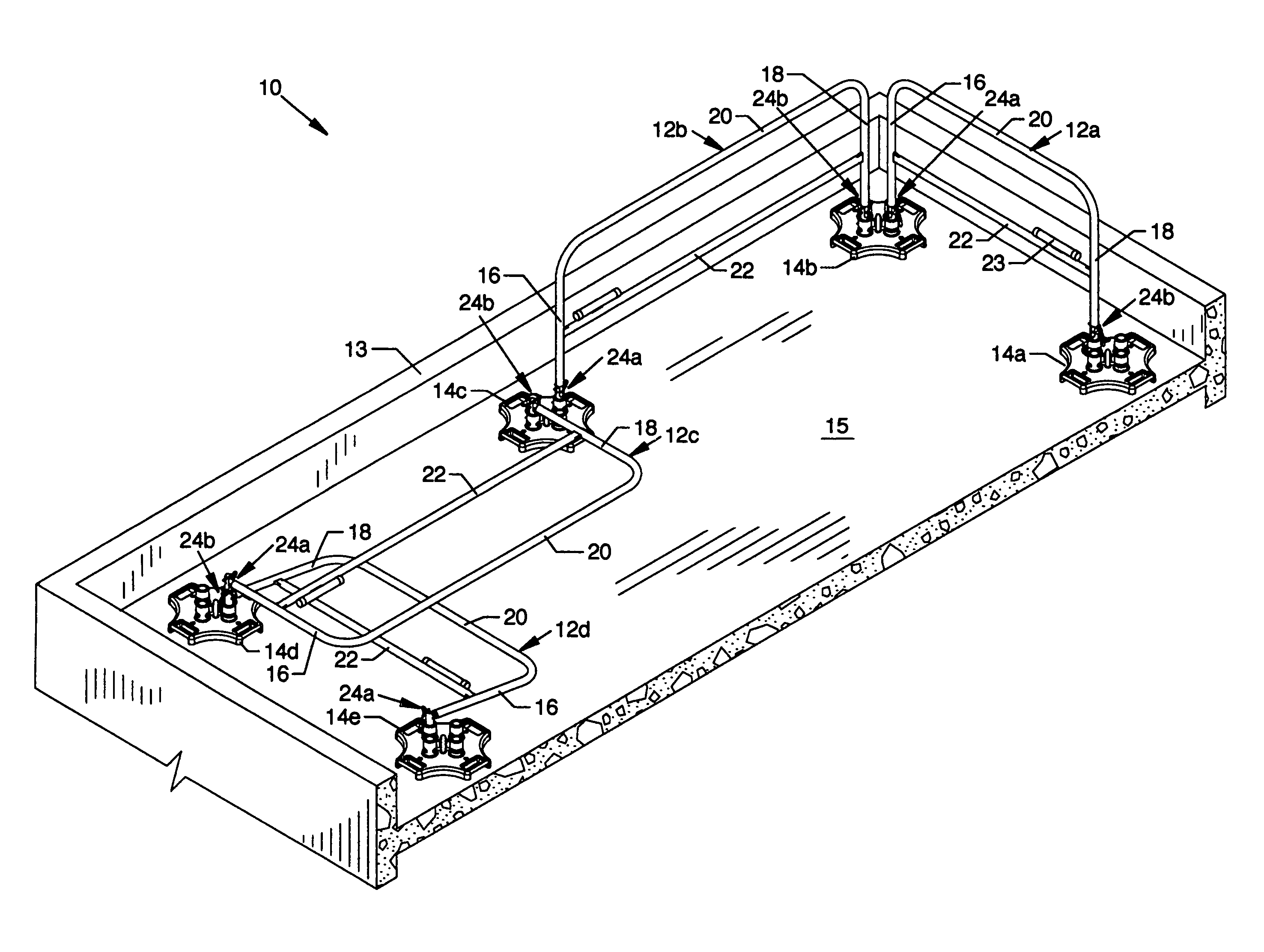
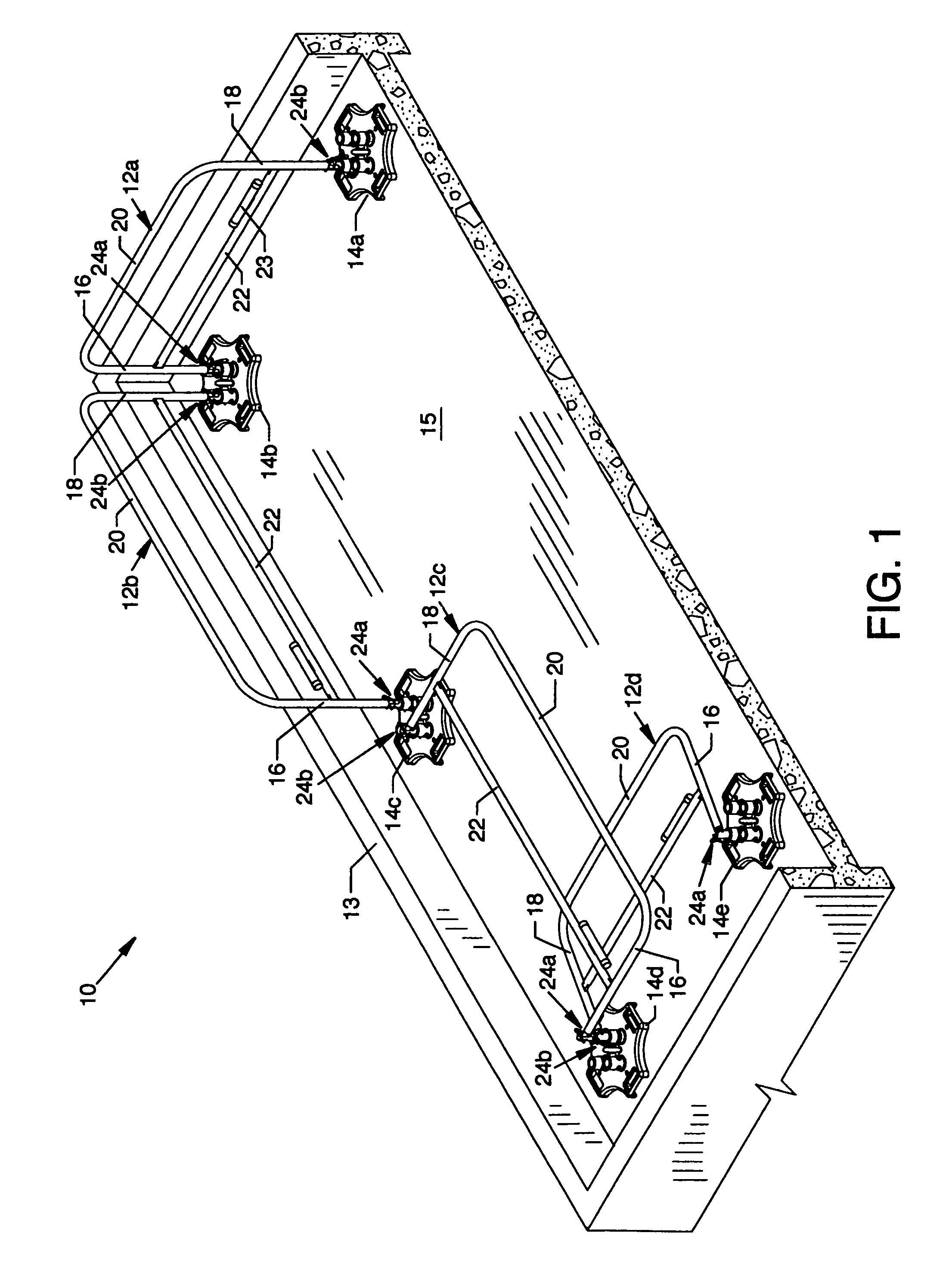
[0038]FIG. 1 is an isometric view of the collapsible safety rail system 10, the present invention, including a plurality of similarly constructed collapsible safety rail assemblies 12a-12d and a plurality of bases 14a-14e of substantial weight and size, each connectively associated with one or more collapsible safety rail assemblies 12a-12d. For purposes of illustration and example, the collapsible safety rail system 10 is shown in use for protection along the edge of a wall section 13 extending above the top surface of a roof 15 where the collapsible safety rail system 10 is shown partially in the protective mode and partially in the collapsed mode. Collapsible safety rail assemblies 12a and 12b are shown in the protective mode of operation being vertically erected with respect to the bases 14a-14c for prevention of access across the collapsible safety rail assemblies 12a and 12b. Collapsible safety rail assemblies 12c and 12d are shown in the collapsed mode of operation being subs...


PUM


Abstract

A collapsible safety rail system for providing a portable or permanent protective barrier to provide for fall prevention from elevated or other work areas. Lockable pivot assemblies are located between heavy bases and the end posts of collapsible safety rail assemblies. Removable detent pins are utilized to lock the pivot assemblies to maintain the erected position of the collapsible safety rail assemblies in protective vertical orientation or are removed to allow maneuvering of the collapsible safety rail assemblies to a minimum viewable profile position when not required for personnel protection.

Description

CROSS REFERENCES TO RELATED APPLICATIONS[0001]This patent application is related to application Ser. No. 10 / 916,688 entitled “Gate Section and Base for a Safety Rail System” filed on Aug. 11, 2004, now U.S. Pat. No. 6,902,153, which is a divisional of application Ser. No. 10 / 319,992 entitled “Gate Section and Base for Safety Rail System” filed Dec. 16, 2002, now U.S. Pat. No. 6,845,970, which is a continuation-in-part of application Ser. No. 09 / 595,794 entitled “Safety Rail System” filed Jun. 16, 2000, now U.S. Pat. No. 6,554,257.BACKGROUND OF THE INVENTION[0002]1. Field of the Invention[0003]This invention pertains to a safety rail system, and more particularly, pertains to a collapsible safety rail system for providing a portable or permanent protective barrier to provide for fall prevention from elevated or other work areas.[0004]2. Description of the Prior Art[0005]Prior art safety rail systems or other fall prevention systems have been provided to prevent workers or other perso...

Claims


Application Information

Patent Timeline
Patent Type & Authority Patents(United States)
IPC IPC(8): E04G5/14
CPCE04G5/14E04G21/3233Y10S256/02E04H17/14E04G21/3228E04G21/3238E04H17/1448E04H17/1413E04H17/009E04H17/1417E04H17/18E06B11/00
Inventor KENTON, GREGORY S.MERTES, ANTHONY J.
Owner TRACTEL INC
Learn More