Robust multi-tool assembly for hydraulic excavators

a multi-tool, hydraulic excavating technology, applied in mechanical machines/dredgers, soil shifting machines/dredgers, constructions, etc., can solve the problems of tool failure or work failure, not only unacceptable, but also very dangerous, and must occur, and bring mechanical complexity

Active Publication Date: 2019-04-04
AMI ATTACHMENTS
View PDF25 Cites 3 Cited by
  • Summary
  • Abstract
  • Description
  • Claims
  • Application Information

AI Technical Summary

Benefits of technology

[0024]It is an object of the invention to provide an excavator tool capable operating in the most demanding conditions for long periods and far from maintenance and repair facilities as the slightest interruption of work schedules by failure or even simple tool switching can be extremely expensive and ruinous to production schedules in such conditions, or elsewhere.

Problems solved by technology

The power of such machines and the amount of energy involved has and continues to increase with increasingly larger, heavier and more difficult materials and includes not only digging but also breaking and shearing, among others.
Necessarily, hydraulic excavators are designed to carry out a broad range of construction and demolition duties in extremely adverse and highly variable conditions, including high impact loading during initial contacts and continuing work, abrasive debris and severe vibration while working in all manner of solid, semi-solid and liquidy or mixed materials.
Any tool failure or work failure is not only unacceptable but also very dangerous and must occur under tightly controlled conditions.
While convenient, these requirements bring about mechanical complexity as the bucket or other primary working tool is no longer a permanent fixture at the distal end of the stick.
Typical hydraulic cylinders completely expose their hydraulic seals and piston rods to these conditions and full protection is difficult to achieve and expensive to implement while making the attachment tool itself cumbersome and heavy, thereby interfering with the ongoing excavator work.

Method used


Image

  • Robust multi-tool assembly for hydraulic excavators
  • Robust multi-tool assembly for hydraulic excavators
  • Robust multi-tool assembly for hydraulic excavators

Examples


Embodiment Construction

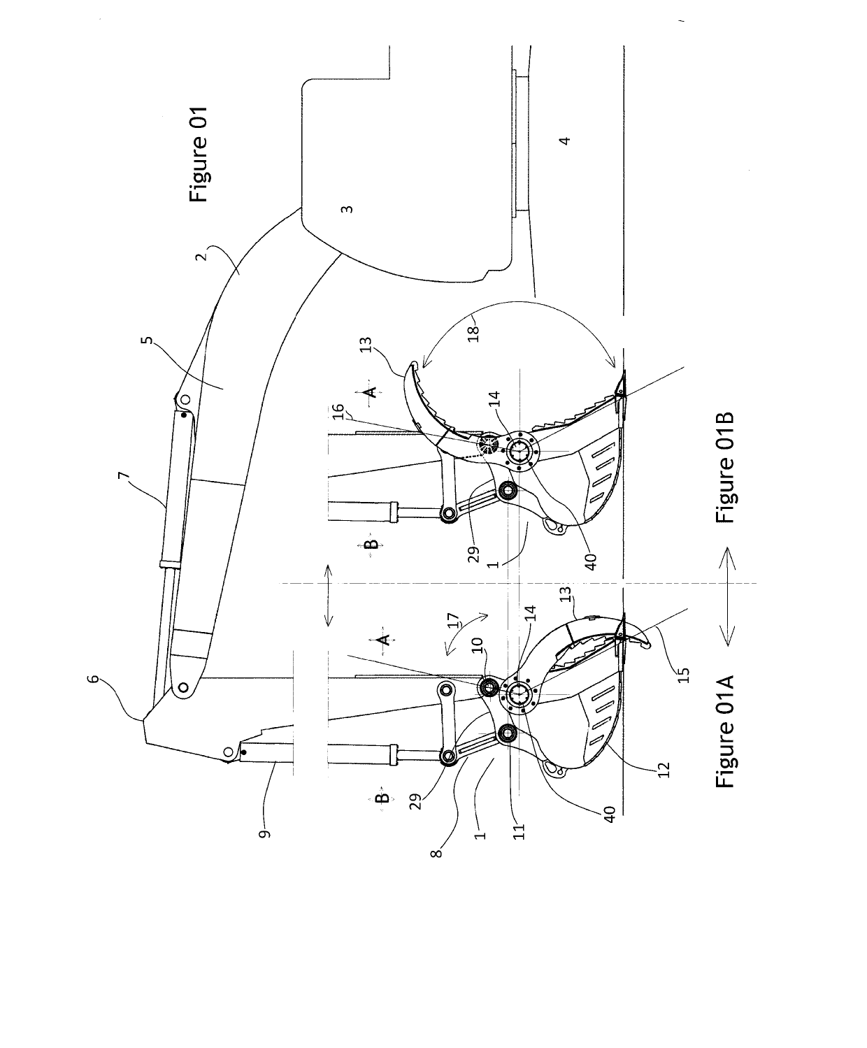
[0043]The hydraulic excavator 2 tool 1 of the invention is shown in a side elevation view in FIG. 01 configured as a bucket 12 plus a gripper thumb 13 connected for controlled relative rotation about axle 14 separate from the main bucket axes of work 10 and 11. FIG. 01a shows the thumb 13 in a fully closed position which FIG. 01b shown the thumb in the full open position.

[0044]All of the operating requirements for the tool assembly 1 are within the working area A between the cab 3, tracks 4, the primary arm or stick 5 and the secondary arm or stick 6 of the excavator while none of these are in the external area B. Tool assembly 1 is operated hydraulically from the cab completely independently of the bucket 12 or the secondary arm 6 or their operating or connecting linkages and thus is under separate operator control.

[0045]As is commonly the case, rotation of stick 5 about stick 6 is driven and maintained by linear hydraulic cylinder 7. Similarly, stick 6 includes a further secondary...


PUM


Abstract

A hydraulic excavator tool adapted to be secured to the distal working end of an excavator boom including a main tool assembly with a tool framework, a spaced apart pair of connection flanges fast with the tool framework, and, a structural tubular casing integral with the tool framework extending across and through the tool framework and through the flanges, plus a rotary hydraulic actuator within the tubular casing extending between the connection flanges and providing a rotational drive motion to a drive axle extending between the connection flanges adapted to provide a controlled rotary drive motion of the axle adjacent the connection flanges, and a working tool framework fast to the axle adjacent each of the connection flanges for relative controlled rotation of the working tool framework about the drive axle between the tool framework and a working position.

Description

PRIORITY[0001]This application claims priority based upon GB provisional applications:[0002]GB-1604983.5, filed 23 Mar. 2016, and,[0003]GB-1701204.8, filed 24 Jan. 2017,FIELD OF THE INVENTION[0004]This invention provides a multiple tool assembly relating to rotatable tools secured to the working distal boom end of hydraulic excavators for controlled relative rotation between a working tool and the assembly framework.BACKGROUND[0005]The overall form of a hydraulic excavator has been well known for decades. There are many examples of such excavators with a 2-boom stick hydraulically and rotationally secured to work within in a vertical plane, itself rotatable about a vertical axis coincident with a engine / cab combination mounted to a pair of tracks. The position and movement of the distal working end of the stick is controlled typically from a operator's cab mounted on the excavator. Although this general design profile is common, the range of sizes and shapes varies considerably due ...

Claims


Application Information

Patent Timeline
Patent Type & Authority Applications(United States)
IPC IPC(8): E02F3/36E02F3/40
CPCE02F3/3622E02F3/365E02F3/3663E02F3/404
Inventor FREY, STEVEN OSCARMYER, DWIGHT COLIN
Owner AMI ATTACHMENTS
Why Eureka
Try Eureka