
Dual wheels with common hub adapter

a technology of hub adapter and dual wheels, which is applied in the direction of wheels, multi-wheel assemblies, trucks, etc., can solve the problems of poor ride quality, high replacement cost, and loose wheels

Active Publication Date: 2014-04-08
HUTCHINSON SA
View PDF24 Cites 24 Cited by
  • Summary
  • Abstract
  • Description
  • Claims
  • Application Information

AI Technical Summary

Benefits of technology

The invention is about a new design for dual wheels that solves problems with previous designs, such as high stress, difficulty in alignment, and poor ride quality. The new design uses a cast hub with two demountable rims or a spindle with a separate hub mount bearing. The arrangement of the dual wheels is also improved to reduce weight, misalignment, and corrosion. Overall, the invention provides a more robust and reliable design for dual wheels.

Problems solved by technology

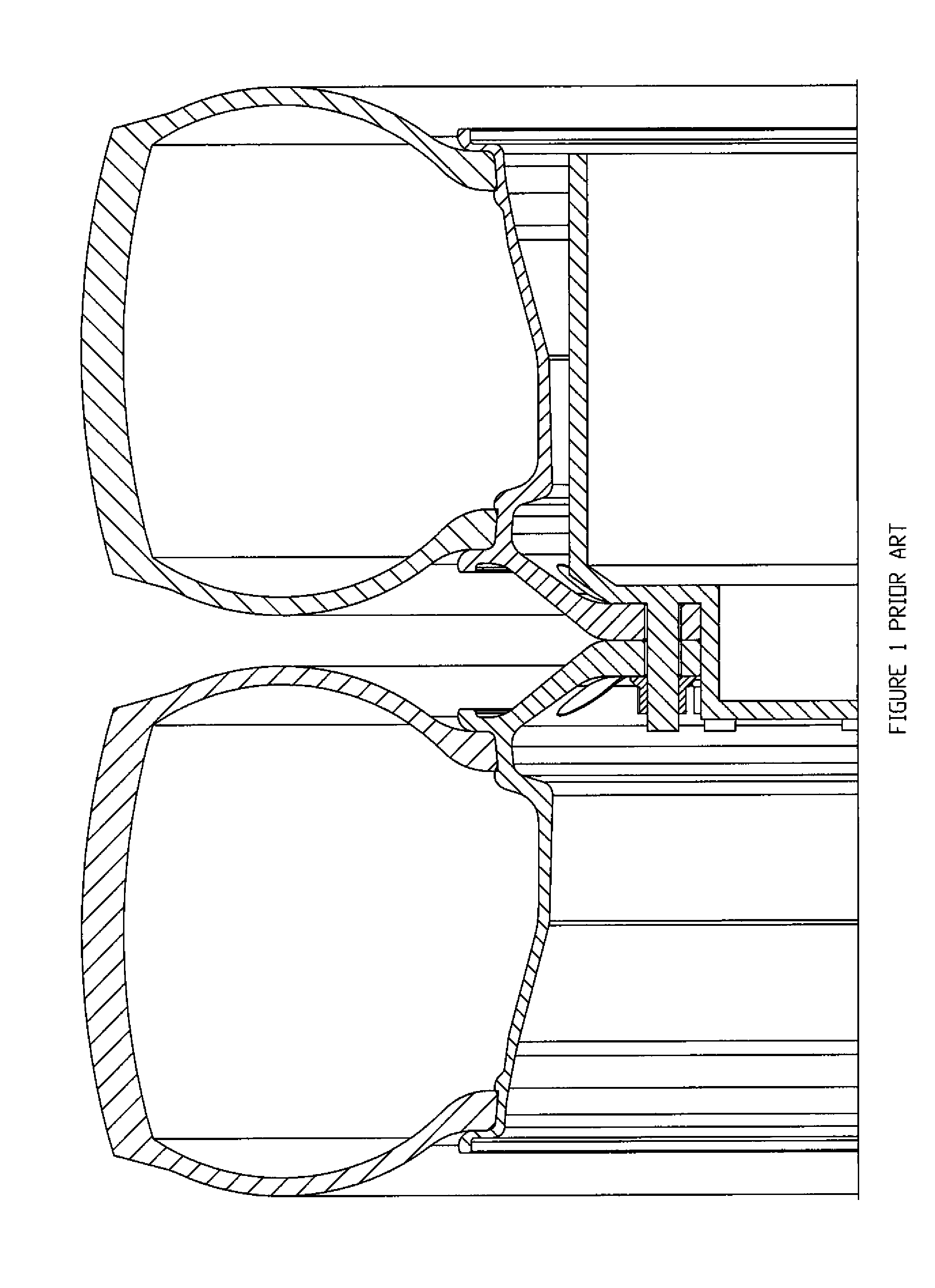
The conventional arrangement shown in FIG. 1 tends to have relatively high stresses in the disc area, the entire wheel often must be replaced in the event of the wheel cracking under load (which can result in higher replacement costs), the studs tend to protrude a further distance from the hub so that they can go through both wheel discs and be secured with a nut, and fretting and corrosion can occur between the two discs of the dual wheels.
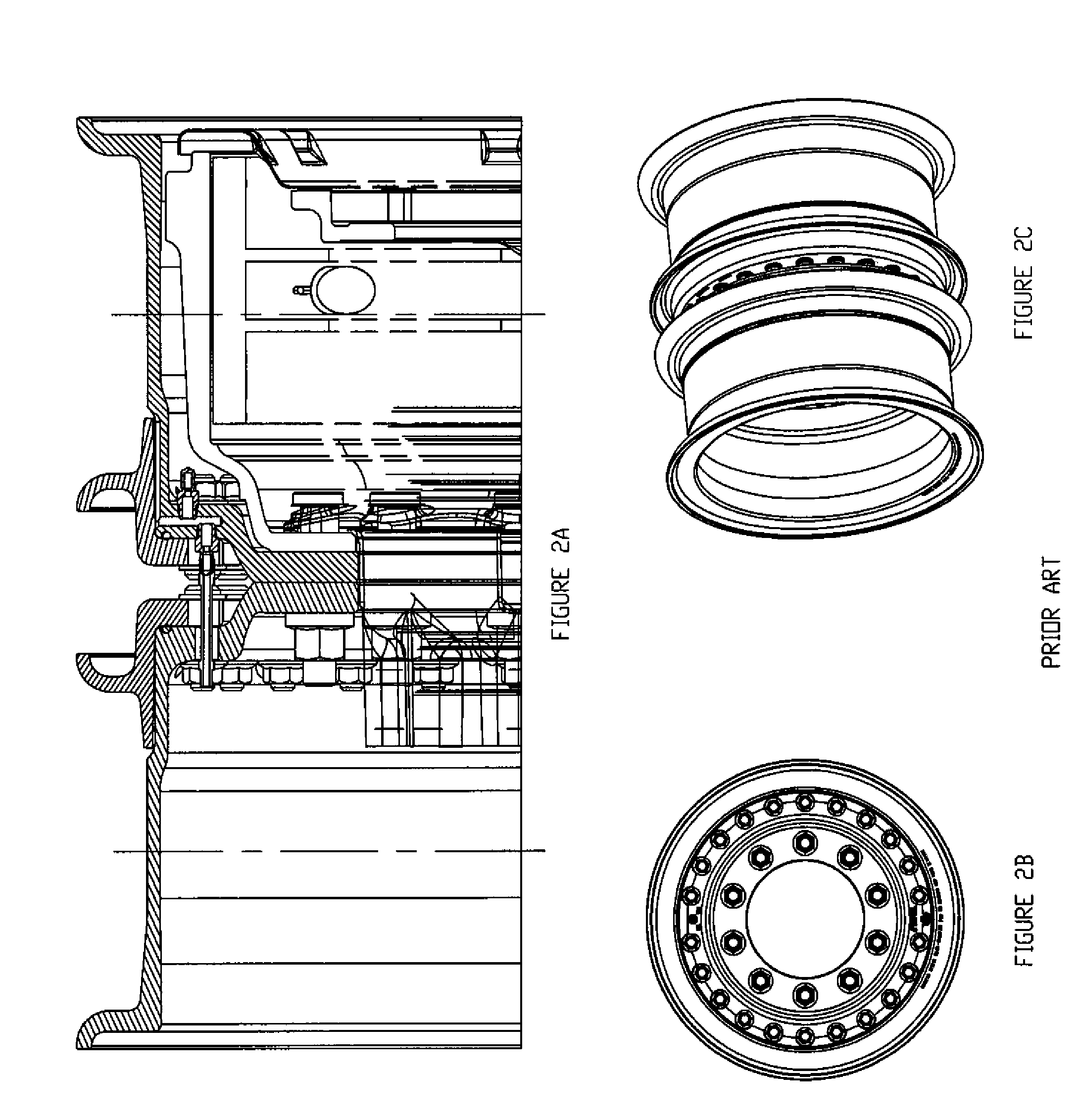
The cast hub of FIGS. 2A-2C tends to be relatively heavy and the assembly tends to be relatively difficult to align properly resulting in poor ride quality, the risk of wheels becoming loose, imbalance, chording of rims if clamps are over-tightened and difficulty in reaching the inflation valve of the inner dual.
Also, maintenance tends to be difficult due to the high number of fasteners, and extremely limited access to the cap screws for the inner dual.
This arrangement tends to include excessive weight, potential for misalignment (which in turn can cause poor ride quality), imbalance, and restricted access to the inflation valve of the inner dual.

Method used


Image

  • Dual wheels with common hub adapter
  • Dual wheels with common hub adapter
  • Dual wheels with common hub adapter

Examples


Embodiment Construction

[0022]It is to be understood that at least some of the figures and descriptions of the invention have been simplified to illustrate elements that are relevant for a clear understanding of the invention, while eliminating, for purposes of clarity, other elements that those of ordinary skill in the art will appreciate may also comprise a portion of the invention. However, because such elements are well known in the art, and because they do not facilitate a better understanding of the invention, a description of such elements is not provided herein.

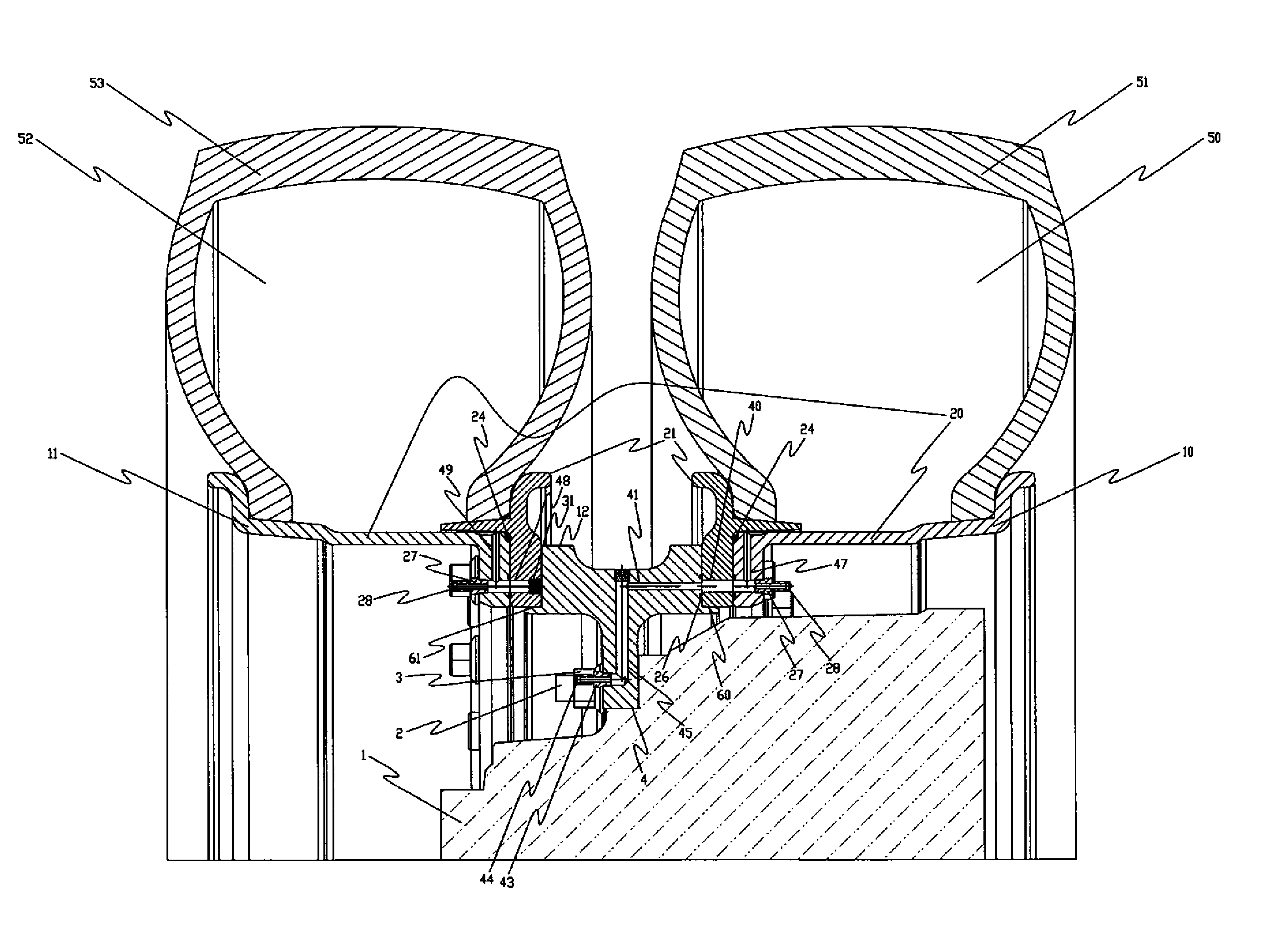
[0023]FIGS. 5A-7 illustrate various embodiments of a dual wheel assembly. FIG. 5A shows an assembly of the dual wheels 10 and 11 coaxially mounted with a central spacer portion or hub adapter 12 and vehicle hub 1. FIG. 6 shows an exploded view of the dual wheels 10 and 11 and hub adapter 12. FIG. 6 shows an exploded view of the inner dual wheel 10. The arrangement of FIG. 7 also applies to outer dual wheel 11.

[0024]Referring to FIG. 7, the i...


PUM


Abstract

A dual wheel assembly for a vehicle having a common hub adapter. The assembly includes an inner wheel having an inner rim; an outer wheel having an outer rim; and a hub portion having a central cylindrical portion disposed between first and second end face portions, wherein the inner rim is mounted to the first end portion, and the outer rim is mounted to the second end face portion. The assembly may further include radially spaced apart holes disposed on the central cylindrical portion, wherein the spaced apart holes have end openings on opposite sides thereof and first and second fasteners extending in opposite directions in an alternating arrangement from the first and second end portions of the hub portion. Each of the first fasteners extends through an end opening of a spaced apart hole and the inner rim, and each of the second fasteners extends through an end opening of a spaced apart hole and the outer rim.

Description

FIELD OF THE INVENTION[0001]This application discloses an invention which is related, generally and in various embodiments, to dual wheels having a common hub.BACKGROUND OF THE INVENTION[0002]A conventional arrangement of dual wheels mounted to a hub is shown in FIG. 1. This arrangement is common in the commercial heavy truck industry. For dual wheel mounting, the hub has protruding studs. The inner dual wheel with tire is assembled onto the hub, then the outer dual wheel with tire is assembled to the hub, and then a flange nut secures both wheels to the hub assembly. Wheels can be centered on the hub or by use of conical or ball seat nuts so that the wheels are centered using the studs. The conventional arrangement shown in FIG. 1 tends to have relatively high stresses in the disc area, the entire wheel often must be replaced in the event of the wheel cracking under load (which can result in higher replacement costs), the studs tend to protrude a further distance from the hub so th...

Claims


Application Information

Patent Timeline
Patent Type & Authority Patents(United States)
IPC IPC(8): B60B11/00
CPCB60B2900/325B60Y2200/14B60B11/06B60B2900/541B60B2900/112B60B11/02
Inventor NOBLANC, OLIVIERRESARE, LARS JOHANPOYRAZLI, AYSELSHERMAN, MATTHEW P.ROGERS, LARRY K.
Owner HUTCHINSON SA
Learn More