
Cable fixing method and cable connecting part

a technology of fixing method and cable, which is applied in the direction of coupling device connection, coupling protective earth/shielding arrangement, manufacturing tools, etc., can solve the problems of large tensile force applied to the connecting part, the operation becomes troublesome in the assembling and maintenance of the vehicle, and the resin connector hardly satisfies all the requests, etc., to achieve high mechanical strength, increase the holding force of the electric wire against the tensile force, and water proo

Active Publication Date: 2014-04-08
HITACHI METALS LTD
View PDF10 Cites 4 Cited by
  • Summary
  • Abstract
  • Description
  • Claims
  • Application Information

AI Technical Summary

Benefits of technology

[0031]According to the present invention, an electric wire or cable is secured to a metallic case by crimping a metallic cylindrical part in such a manner that 0.60≦K≦0.95 is established, wherein a cross-sectional area of the electric wire or cable before crimping the metallic cylindrical part is A, a cross-sectional area of the electric wire or cable after crimping the metallic cylindrical part is B, and B / A is a crimping ratio K. According to this structure, the metallic cylindrical part cuts (bites) into a coating of the electric wire or cable adequately at a crimping point. Since the coating of the electric wire closely contacts with the metallic cylindrical part of the metallic case, there are advantages in that the water proofing property is ensured and the holding force of the electric wire against the tensile force is increased. Furthermore, since the metallic case is used as a case for accommodating a terminal of the electric wire, the connecting part has high mechanical strength against impact from outside, such as bounced pebbles. Therefore, it is possible to connect the electric wire with the electronic equipments and electromotive devices, even in the environment outside the compartment of vehicle, in which the impact due to the bounced pebbles or the water immersion may occur.
[0017]In the method, the metallic case may further comprise a terminal holder accommodating part, a terminal press-fitted to a core of the cable is fixed to a terminal holder comprising an insulative material, and the terminal holder is accommodated in and fixed to the terminal holder accommodating part to provide a connector.
[0033]Still further, although the cable connecting part of present invention has a simple structure, it can be used even in the environment outside the compartment of vehicle. Furthermore, it is possible to provide the cable connecting part with sufficient water proofing property, holding force of the electric against the tensile force, and mechanical strength. In addition, since the cable connecting part has a little number of the components and a simple structure, it is possible to reduce the fabrication cost.

Problems solved by technology

Further, since mud or snow may be bonded to the electric wire in the environment outside the compartment of vehicle, a large tensile force may be applied to the connecting part (connector) for connecting between the electric wire and the equipment from the electric wire due to oscillation.
As a result, there is a problem in that an operation becomes troublesome in assembling and maintenance of the vehicle.
However, there is a disadvantage in that the connector made of the resin hardly satisfies all the requests such as water proofing property, holding force of the electric wire against the tensile force, and mechanical strength.

Method used


Image

  • Cable fixing method and cable connecting part
  • Cable fixing method and cable connecting part
  • Cable fixing method and cable connecting part

Examples


first embodiment

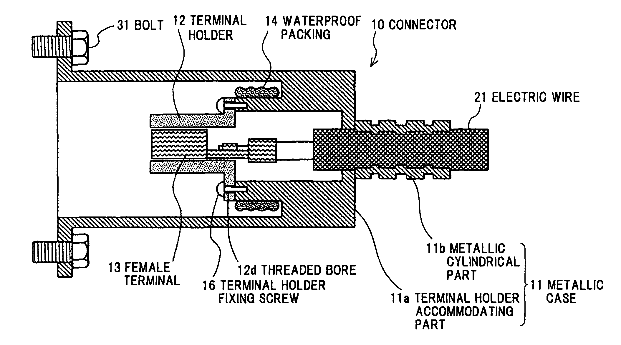
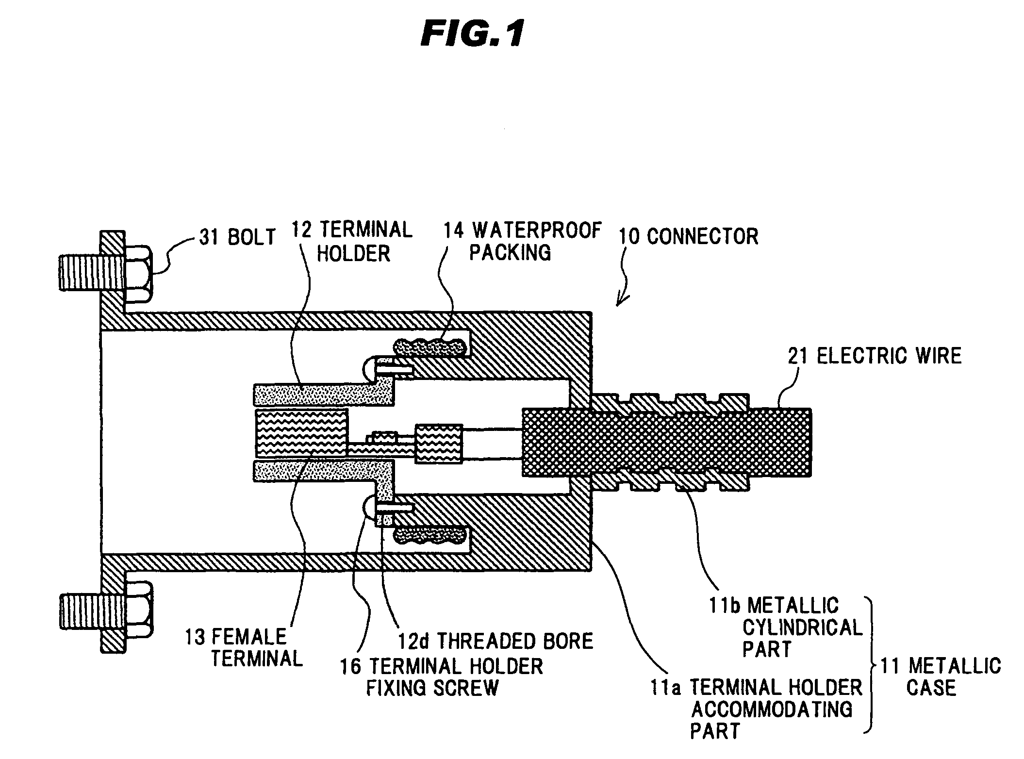
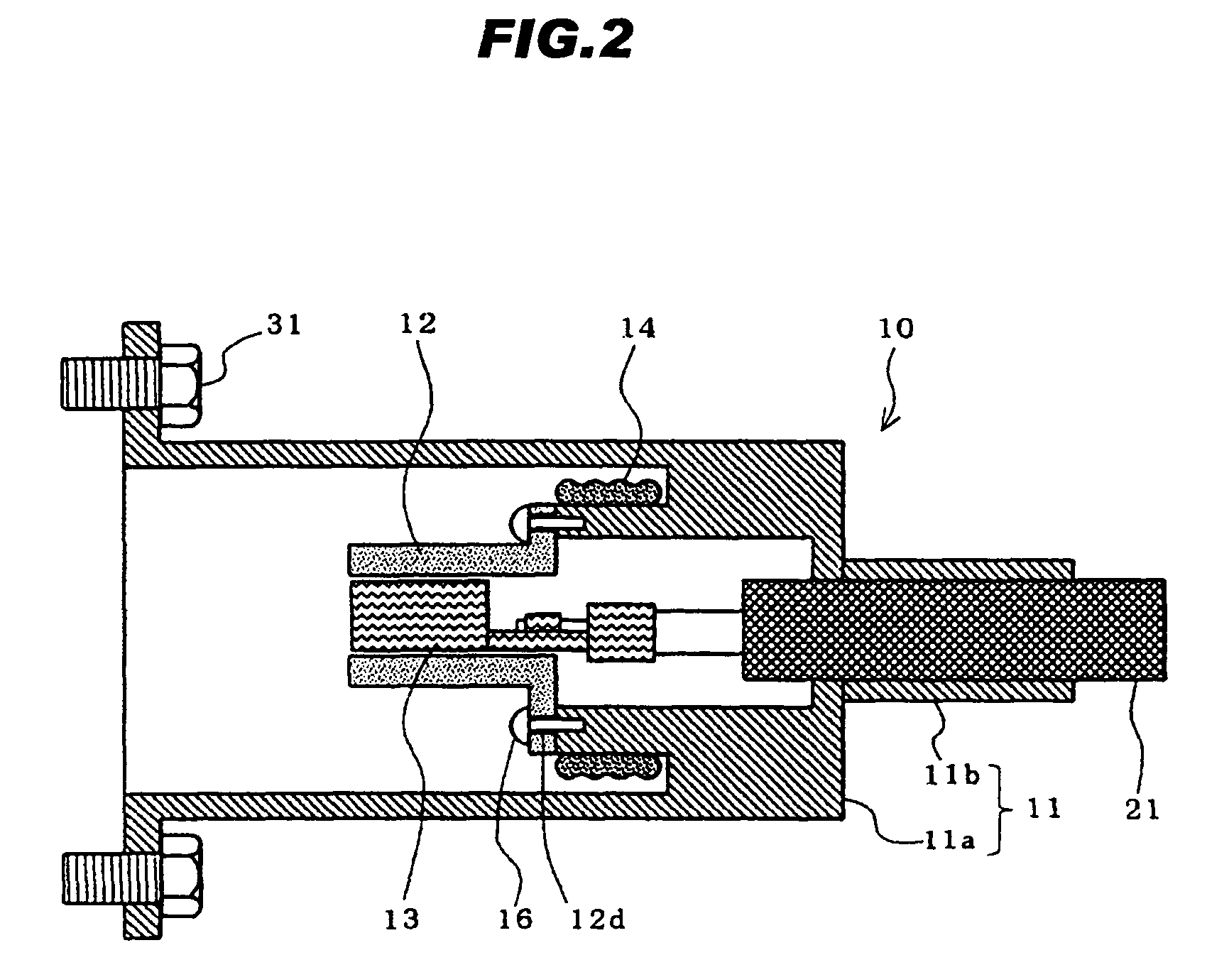
[0048]FIG. 1 is a longitudinal cross sectional view of a connector (female connector) 10 in the first embodiment according to the present invention. FIG. 2 is a longitudinal cross sectional view of the connector 10 shown in FIG. 1 before crimping.

(Total Structure of the Connector 10)

[0049]Referring to FIG. 1, the connector 10 comprises a metallic case 11 comprising a terminal holder accommodating part 11a which is made of metal and a metallic cylindrical part 11b. In the connector 10, an electric wire 21 is inserted into the metallic case 11 comprising the terminal holder accommodating part 11a and the metallic cylindrical part 11b, and a female terminal 13 press-fitted (crimped) to a wire of the electric wire 21 is fixed to a terminal holder 12 comprising an insulative material such as PBT or nylon. Thereafter, the terminal holder 12 is accommodated in the terminal holder accommodating part 11a, as shown in FIG. 2, and the electric wire 21 is fixed to the metallic case 11 by crimpi...

second embodiment

[0069]FIG. 6 is a cross sectional view of a male connector 80 in the second embodiment according to the present invention.

[0070]In the first embodiment, the female connector 10 is used. However, configuration of the metallic case, the terminal holder and the terminal may be appropriately changed. For example, as shown in FIG. 6, the male connector 80 may be provided in place of the female connector 10, by replacing the female terminal 13 with a male terminal 15.

(Examples of the Cable)

[0071]FIGS. 7A to 7D are diagrams showing examples of the electric wire (cable) to be used in the present invention.

[0072]FIGS. 7A and 7B shows an electric wire 22 having two power lines or two signal lines. The two power lines (or the two signal lines) 22a, 22a, each of which comprises a conductor 21a and an insulator 21b provided at an outer periphery of the conductor 21a, are twisted and a sheath 21c is provided at an outer periphery of the twisted insulated wires via a filler 21e.

[0073]FIGS. 7C and...

third embodiment

[0080]Next, a fixing structure 100 in the third embodiment will be explained below.

[0081]FIG. 10 is a longitudinal cross sectional view of the fixing structure 100 in the third embodiment according to the present invention.

[0082]FIGS. 11A and 11B are diagrams showing a metallic case 101 used for the fixing structure 100 in the third embodiment according to the present invention, wherein FIG. 11A is a front view thereof, and FIG. 11B is a side view thereof.

[0083]Referring to FIG. 10, the fixing structure 100 in the third embodiment according to the invention comprises a metallic case 101 comprising a metallic cylindrical part 101b, which accommodates a part of a cable 21 in a longitudinal direction, in which the cable 21 is fixed to the metallic case 101 by crimping a cable connecting part 104 of the metallic cylindrical part 101b. More particularly, in the fixing structure 100, the metallic case 101 is connected to the cable 21 by crimping the metallic cylindrical part 101b in such ...


PUM

PropertyMeasurementUnit
tensile forceaaaaaaaaaa
thicknessaaaaaaaaaa
diameteraaaaaaaaaa

Abstract

A cable fixing method and a cable connecting part for a connector. In the cable fixing method and the cable connecting part, a part of a cable in a longitudinal direction is inserted into a metallic cylindrical part of a metallic case; and the cable is fixed to the metallic case by crimping the metallic cylindrical part which accommodates the part of the cable in the longitudinal direction in such a manner that 0.60≦K≦0.95 is established, when a cross-sectional area of the cable before crimping the metallic cylindrical part is A, a cross-sectional area of the cable after crimping the metallic cylindrical part is B, and B / A is a crimping ratio K.

Description

[0001]The present application is based on Japanese patent application No. 2009-80085 filed on Mar. 27, 2009, Japanese patent application No. 2009-281316 filed on Dec. 11, 2009, and Japanese patent application No. 2010-024255 filed on Feb. 5, 2010, the entire contents of which are incorporated herein by reference.BACKGROUND OF THE INVENTION[0002]1. Field of the Invention[0003]The present invention relates to a cable fixing method and a cable connecting part, more particularly, to a cable fixing method and a cable connecting part for a cable to be used in swinging parts or the like in vehicles, robots and the like.[0004]2. The Related Art[0005]In vehicles such as automobile, various electronic equipments and electromotive equipments are used. Control signal, electric power or the like is transmitted to these electronic equipments or the electromotive equipments via an electric wire installed in the vehicle. A connector suitable for connecting this electric wire to the electronic equip...

Claims


Application Information

Patent Timeline
Patent Type & Authority Patents(United States)
IPC IPC(8): H01R4/10
CPCH01R4/185Y10T29/49002Y10T29/49925
Inventor ESHIMA, HIROTAKA
Owner HITACHI METALS LTD
Learn More