Method for determining the location of impacts by acoustic imaging

a technology of acoustic imaging and location determination, applied in direction finders using ultrasonic/sonic/infrasonic waves, instruments, etc., can solve problems such as failure to determine the location of impacts, synchronization problems in processing units,

Active Publication Date: 2014-04-08
ELO TOUCH SOLUTIONS INC
View PDF23 Cites 47 Cited by
  • Summary
  • Abstract
  • Description
  • Claims
  • Application Information

AI Technical Summary

Problems solved by technology

Yet, the time origin in such a method is not correctly determined, leading to synchronization problems in the processing unit.
In consequence, failures to determine the location of impacts occur.

Method used


Image

  • Method for determining the location of impacts by acoustic imaging
  • Method for determining the location of impacts by acoustic imaging
  • Method for determining the location of impacts by acoustic imaging

Examples


first embodiment

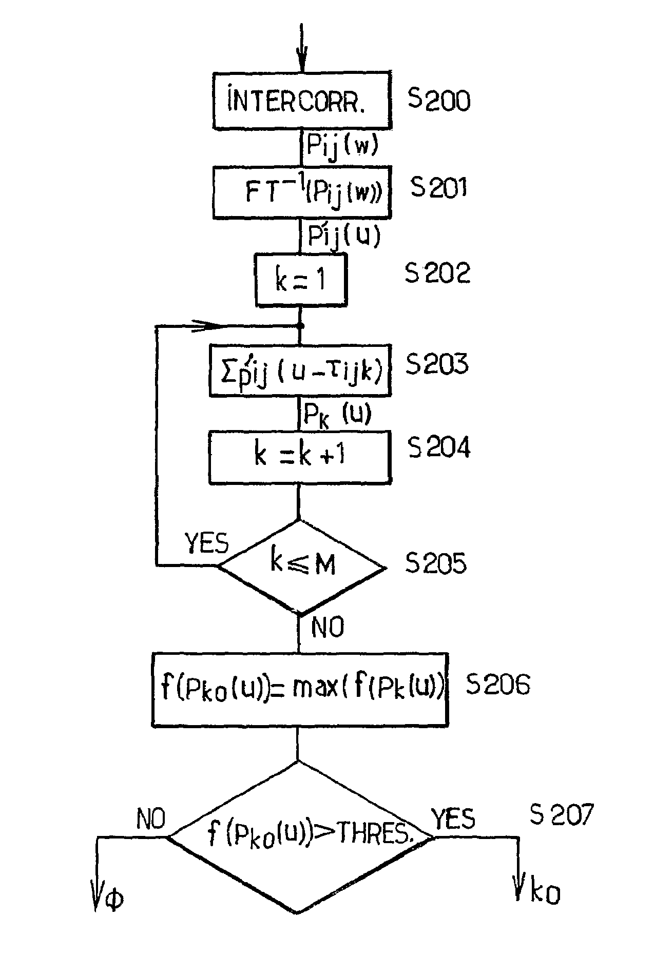
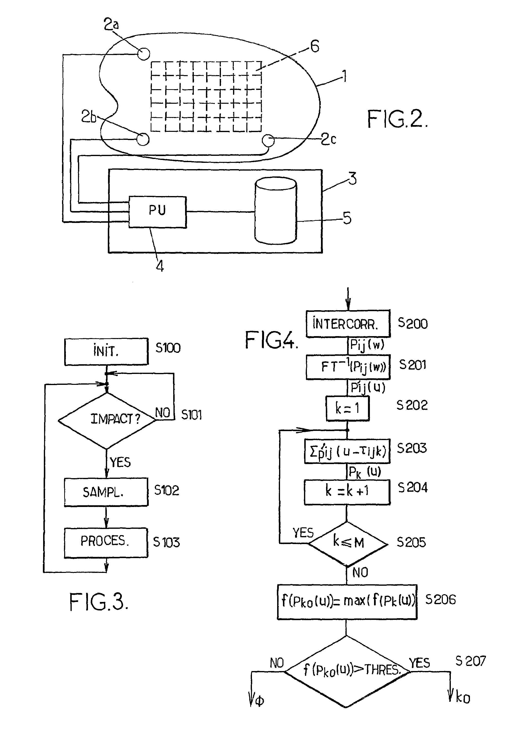
[0072]Then, in step S201, inverse Fourier transforms of the Pij(ω) are computed. the object material is non dispersive. This means that the wave propagation velocity of an acoustic signal does not depend on the frequency of this signal. In consequence, the waveform of a sensed signal propagated in this material is substantially equals to the original signal delayed of a delay which is a function of the material velocity and the distance between the source and the sensor. In this case, the inverse Fourier transform may be a usual inverse Fourier Transform or an inverse Fast Fourier Transform.

[0073]At step S202, k is initialized to 1 in order to carry out thereafter the computation of the sum Pk(u)=Σp′ij(u−τijk) (S203) for each area k of the surface, where p′ij(u) is the inverse Fourier transform of Pij(ω). In the current case of non dispersive material, τijk are delays based on the difference between respectively the distance from the area k to the sensor i and the distance from the...

second embodiment

[0090]However, in the case of dispersive material, a second embodiment is provided by the invention. The main difference in this embodiment is that the inverse Fourier transform of step S201 is a dispersion compensate Fourier transform. Indeed, a dispersive material is a material in which an acoustic signal propagation velocity depends on the frequency of the signal. In consequence, the waveform of a sensed signal propagated in this material is different from the original signal waveform. In this case, the dispersion compensate Fourier transform, as explained below, has to compensate the deformation of the signal due to propagation.

[0091]According to the proceeding of the Review of Progress in Quantitative Non-Destructive Evaluation entitled “A signal processing technique to remove the effect of dispersion from guided wave signals” from P. D. Wilcox & al, it is possible to determine the distance of the source a sensed acoustic signal with help of the following formula:

[0092]h⁡(x)=∫-...


PUM


Abstract

A method for determining the location of an impact on a surface (1) comprising N acoustic sensors (2a, 2b, 2c), transmitting a sensed signal si(t) to a processing unit (4) comprises the following steps (a) computing P intercorrelation products (b) calculating P inverse Fourier transforms p′ij (u) (c) computing for each area k, Pk(u)=ΣP′ij (u−τijk); d) finding k0, where a characterizing value of Pk0 (u) is greater than a given threshold value.

Description

CROSS-REFERENCE TO RELATED APPLICATIONS[0001]This application is being filed as a U.S. National Stage under 35 U.S.C. 371 of International Application No. PCT / EP2005 / 005207, filed on Apr. 13, 2005, the contents of which is hereby incorporated by reference in its entirety.FIELD OF THE INVENTION[0002]The present invention relates to a method for determining the location of impacts on an object and a device using this method.BACKGROUND OF THE INVENTION[0003]A known method for determining the location of impacts on an object is based on acoustic image generation. According to this method, a surface of the object is subdivided in M areas, for example like an array, and N acoustic sensors are fixed for example on the surface. Each acoustic sensor i is arranged to receive an acoustic signal generated from an impact on the object surface and to transmit a sensed signal si(t) to a processing unit.[0004]For each area k of the array, the sensed signals si(t) are delayed of a time delay compens...

Claims


Application Information

Patent Timeline
Patent Type & Authority Patents(United States)
IPC IPC(8): G06F3/043
CPCG01N29/50G01N29/14G01N29/46G01N29/4472G01N29/069G06F3/043
Inventor ING, ROS, KIRI
Owner ELO TOUCH SOLUTIONS INC
Why Eureka
Try Eureka