Gas turbine operation control device and operation control method

a technology of operation control device and operation control method, which is applied in the direction of machines/engines, process and machine control, instruments, etc., can solve the problems of grid code demand response for shaft output, inability to meet the desired load, and inability to obtain the desired load, etc., to achieve the effect of improving load responsiveness and increasing the airflow of the compressor

Active Publication Date: 2014-04-08
MITSUBISHI POWER LTD
View PDF12 Cites 6 Cited by
  • Summary
  • Abstract
  • Description
  • Claims
  • Application Information

AI Technical Summary

Benefits of technology

[0021]An object of the present invention is to provide a gas turbine operation control device and a gas turbine operation control method that are capable of restricting a turbine inlet temperature to within the overshoot limit range and that are also capable of satisfying the Grid Code demand response for the shaft output.
[0043]With the present invention, when the output of the generator is in a high load band at or above a predetermined value, or when the degree of opening of the inlet guide vane is in a standard fully-open state, in which the system frequency declines to or below a predetermined threshold value, thus activating the frequency low signal, the intake air flow rate of the compressor is increased by forcing the degree of opening of the inlet guide vane into the emergency fully-open state; therefore, an advantage is afforded in that it is possible to restrict the turbine inlet temperature to within the overshoot limit range, as well as to satisfy the Grid Code demand response for the shaft output due to an increase in the amount of air; and, additionally, because the temperature adjustment setting can be relaxed by the temperature controller to match the degree of opening of the inlet guide vane, load responsiveness can be improved.

Problems solved by technology

In response to a load increase in accordance with a control factor in the case where the frequency declines in governor-free operation at a high load, or in response to a load increase command, with conventional technologies, fuel for the gas turbine 100 is increased; however, because temperature adjustment, on the other hand, is operated from the viewpoint of device protection, such as avoiding device damage due to an increase in the combustion temperature (turbine inlet temperature), a desired load may not be obtained.
Also, on the other hand, when the overshoot of the turbine inlet temperature is not allowed from the viewpoint of device protection, the Grid Code demand response for the shaft output, shown in FIG. 19(c), may not be satisfied.

Method used


Image

  • Gas turbine operation control device and operation control method
  • Gas turbine operation control device and operation control method
  • Gas turbine operation control device and operation control method

Examples


first embodiment

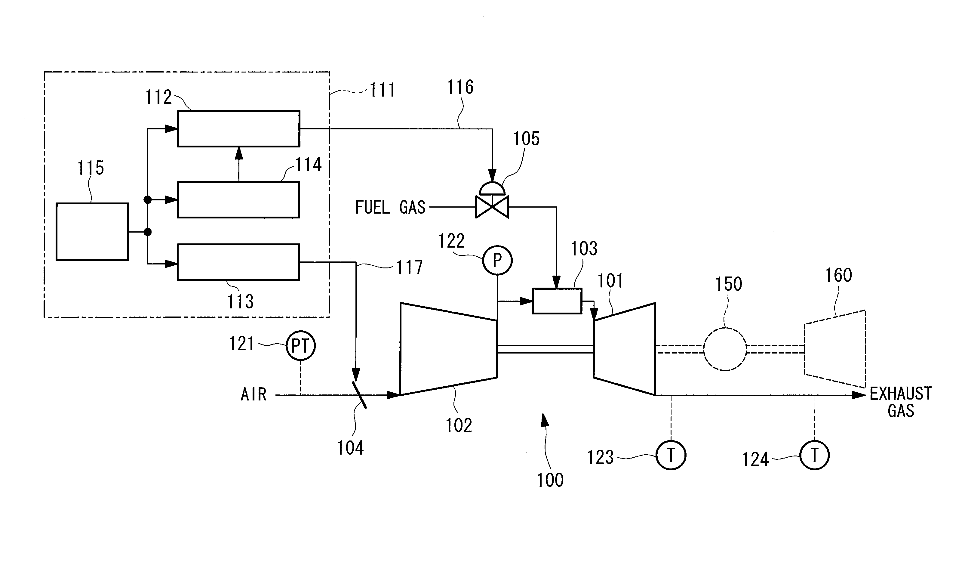
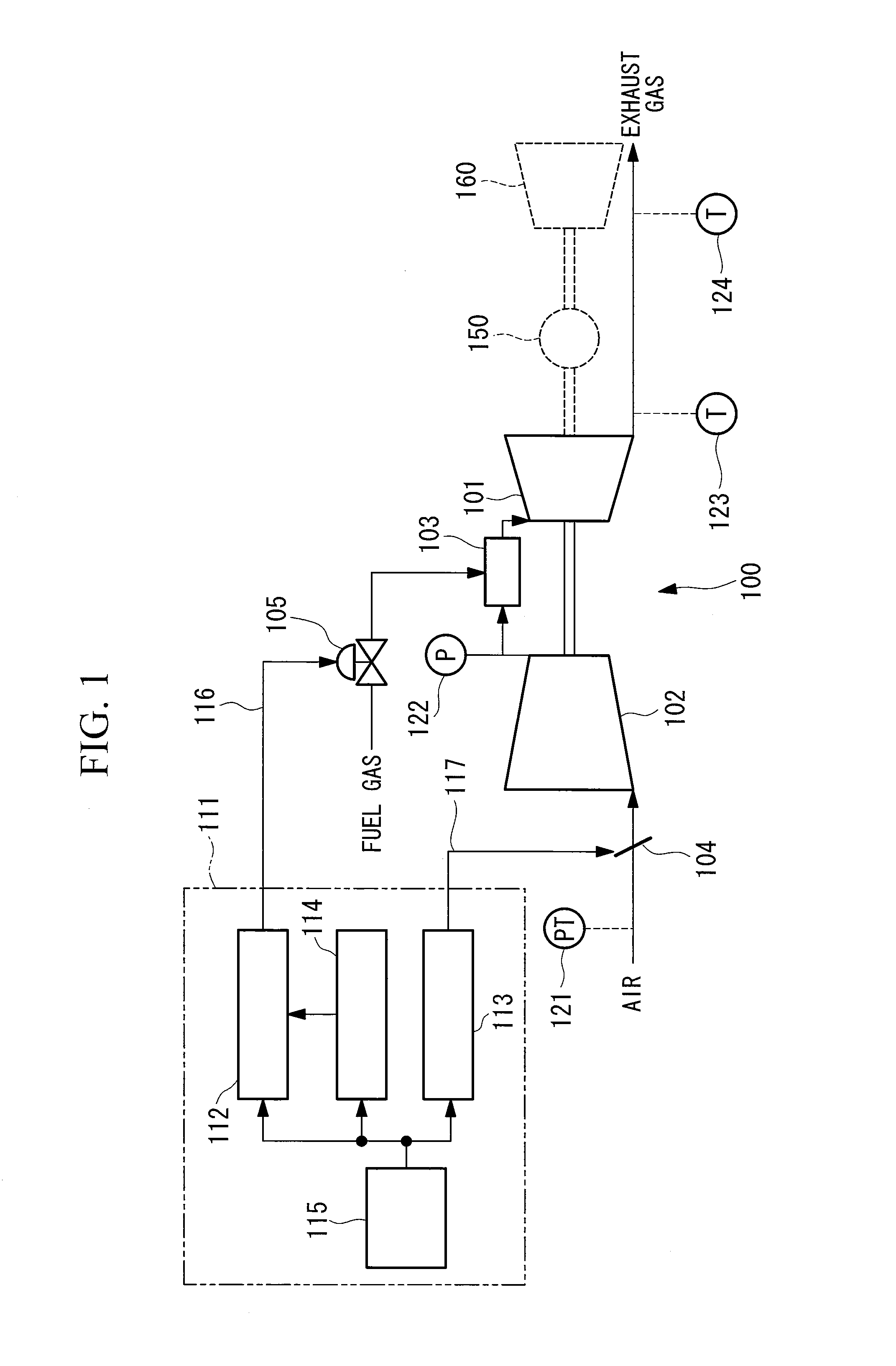
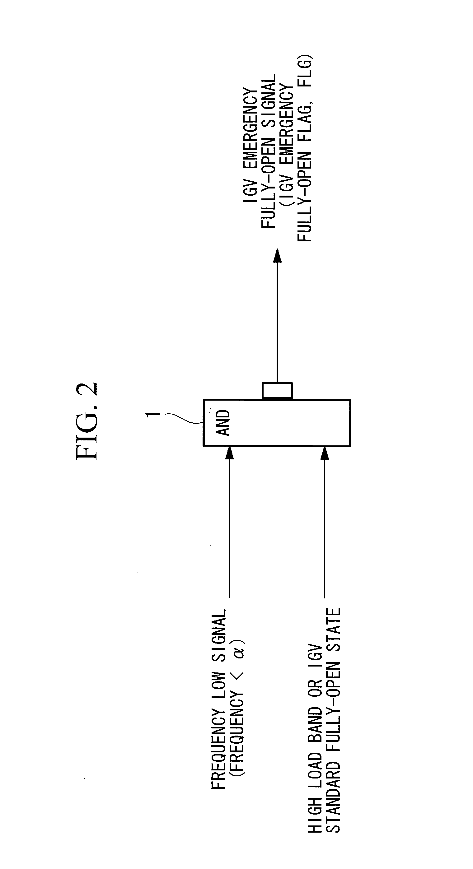
[0091]A gas turbine operation control device and an operation control method according to a first embodiment of the present invention will be described, referring to FIGS. 1 to 7. Here, FIG. 1 is a configuration diagram of the gas turbine operation control device according to the first embodiment of the present invention and, in the diagram, the same reference signs are assigned to portions overlapping with FIG. 14 (conventional example). In addition, FIG. 2 is a specific configuration diagram of an IGV control flag generator in the first embodiment. FIG. 3 is a specific configuration diagram of an IGV controller. FIG. 4 is a configuration diagram of a portion that generates a temperature adjustment setting, EXREF, used in a temperature controller for blade path temperature control and exhaust gas temperature control. FIGS. 5A and 5B are explanatory diagrams for explaining functions in various function units in the temperature controller. FIG. 6 is a configuration diagram of a porti...

second embodiment

[0121]Next, a gas turbine operation control device and operation control method according to a second embodiment of the present invention will be described, referring to FIGS. 8 and 9. Here, FIG. 8 is a configuration diagram of a portion that generates a temperature adjustment setting, EXREF, in a temperature controller 114 of the second embodiment of the present invention, and FIGS. 9A through 9C are explanatory diagrams that explain switching of the temperature adjustment setting, EXREF.

[0122]Note that the feature of this embodiment, as compared with the configuration of the temperature controller 114 of the first embodiment, is the addition of an advance signal generator (first correction portion) 200 that calculates a rate of change of the degree of opening of the inlet guide vane 104, thereby calculating a correction amount in accordance with the rate of change, and that corrects the settings of the temperature adjustment setting, EXREF, by switching in accordance with the degr...

third embodiment

[0130]Next, a gas turbine operation control device according to a third embodiment of the present invention will be described referring to FIG. 10. Here, FIG. 10 is a configuration diagram of the blade path temperature controller of the temperature controller 114 of the third embodiment of the present invention, and the portion that generates the temperature adjustment setting, EXREF, is omitted, assuming that the configuration of the first embodiment or the second embodiment will be used therefor. In addition, the overall configuration of the gas turbine operation control device, the configuration of the IGV controller 113, and the configuration of the fuel controller 112 are equivalent to those in the first embodiment (FIGS. 1, 2, and 7), and descriptions of individual components thereof will be omitted.

[0131]In FIG. 10, the blade path temperature controller in the temperature controller 114 of this embodiment is configured having signal generators (SG15) 301, (SG16) 303, (SG17) 3...


PUM


Abstract

Provided is a gas turbine operation control device and operation control method that are capable of suppressing turbine inlet temperature and of satisfying the demand response for shaft output. An IGV emergency fully-open flag is activated when the output of a generator is in a high load band at or above a predetermined value, and the like. When the IGV emergency fully-open flag is activated, the degree of opening of an inlet guide vane is set to a predetermined degree of opening, a temperature adjustment setting is set by switching in accordance with the degree of opening of the inlet guide vane, and an exhaust gas temperature setting value or a blade path temperature setting value of a turbine, for controlling the fuel supply amount for a combustor, is generated based on the temperature adjustment setting.

Description

TECHNICAL FIELD[0001]The present invention relates to a gas turbine operation control device and operation control method, and relates particularly to a gas turbine operation control device and operation control method that are capable of containing a turbine inlet temperature within an overshoot limit range, in response to a frequency fluctuation, and that are also capable of satisfying the Grid Code demand response for the shaft output.BACKGROUND ART[0002]In general, a gas turbine used in a power plant and the like combusts fuels sprayed into the air compressed in a compressor and gains output by guiding the high-temperature, high-pressure combustion gas obtained as a result to a turbine. A basic configuration of such a gas turbine is shown in FIG. 14. A gas turbine 100 is provided with a compressor 102, a combustor 103, and a turbine 101. The combustor 103 is supplied with air compressed in the compressor 102 and fuel gas whose flow rate is adjusted by a fuel flow rate adjusting ...

Claims


Application Information

Patent Timeline
Patent Type & Authority Patents(United States)
IPC IPC(8): F02C9/00G05D5/00
CPCF01D17/16F01D21/12F02C9/20F02C9/22F02C9/28F02C9/38F02C9/46F02C9/54
Inventor SONODA, TAKASHISAITO, AKIHIKONAKAMURA, SHINSUKE
Owner MITSUBISHI POWER LTD
Why Eureka
Try Eureka