Vacuum cleaner

a vacuum cleaner and vacuum technology, applied in the field of vacuum cleaners, can solve problems such as negative influence on the performance of vacuum cleaners, and achieve the effect of contributing to the efficiency of the separation process and sufficiently high energy density of rotating air

Active Publication Date: 2014-04-15
VERSUNI HLDG BV
View PDF18 Cites 24 Cited by
  • Summary
  • Abstract
  • Description
  • Claims
  • Application Information

AI Technical Summary

Benefits of technology

[0003]It is an object of the invention to provide a vacuum cleaner with a rotatable separator, whereby damaging of the separator by relatively heavy particles is being prevented.

Problems solved by technology

The heavier particles might damage the separator due to which an unbalance of the rotating separator might occur, which will negatively influence the performance of the vacuum cleaner, especially at high rotational speeds.

Method used


Image

  • Vacuum cleaner
  • Vacuum cleaner
  • Vacuum cleaner

Examples


Embodiment Construction

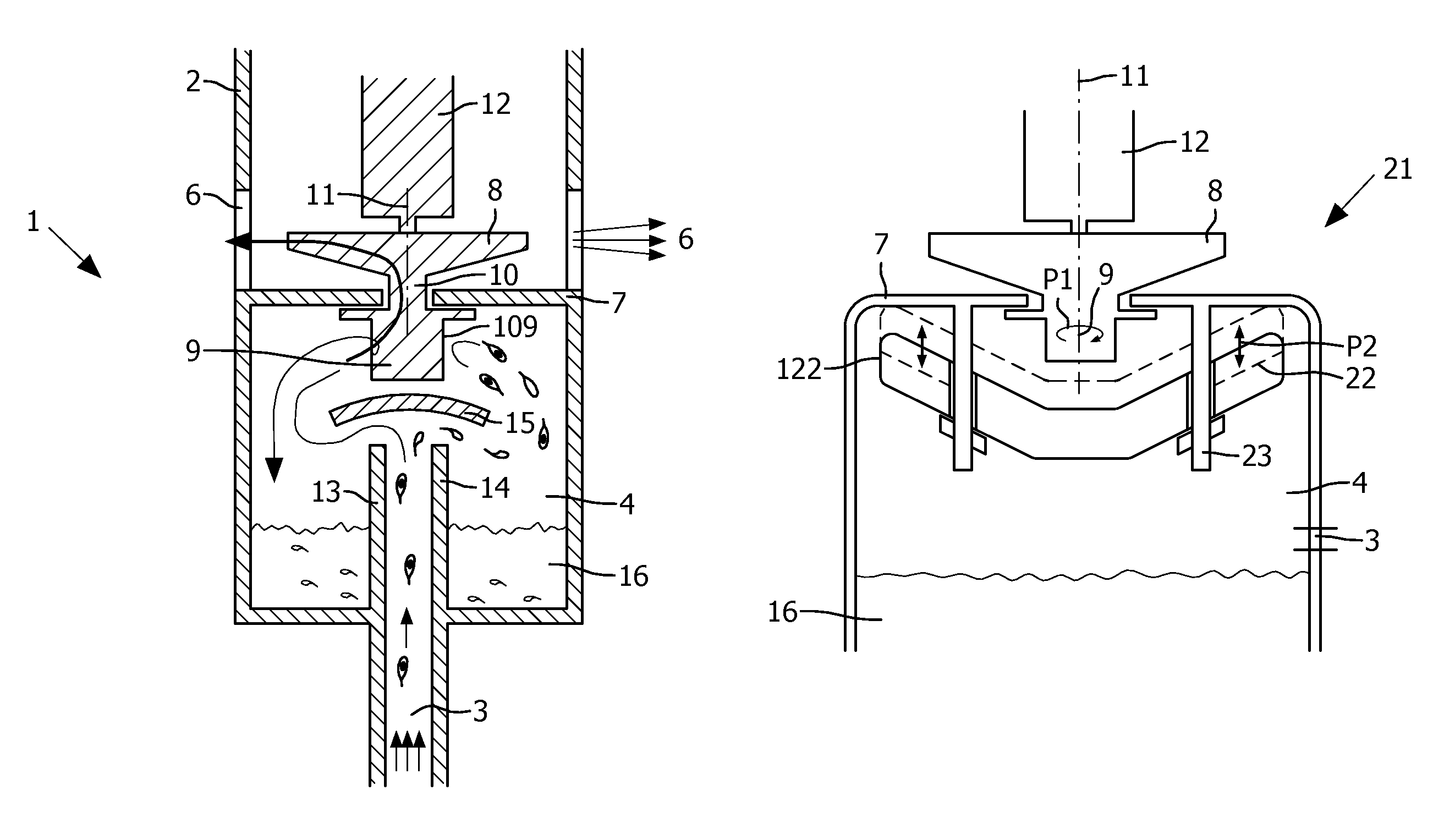
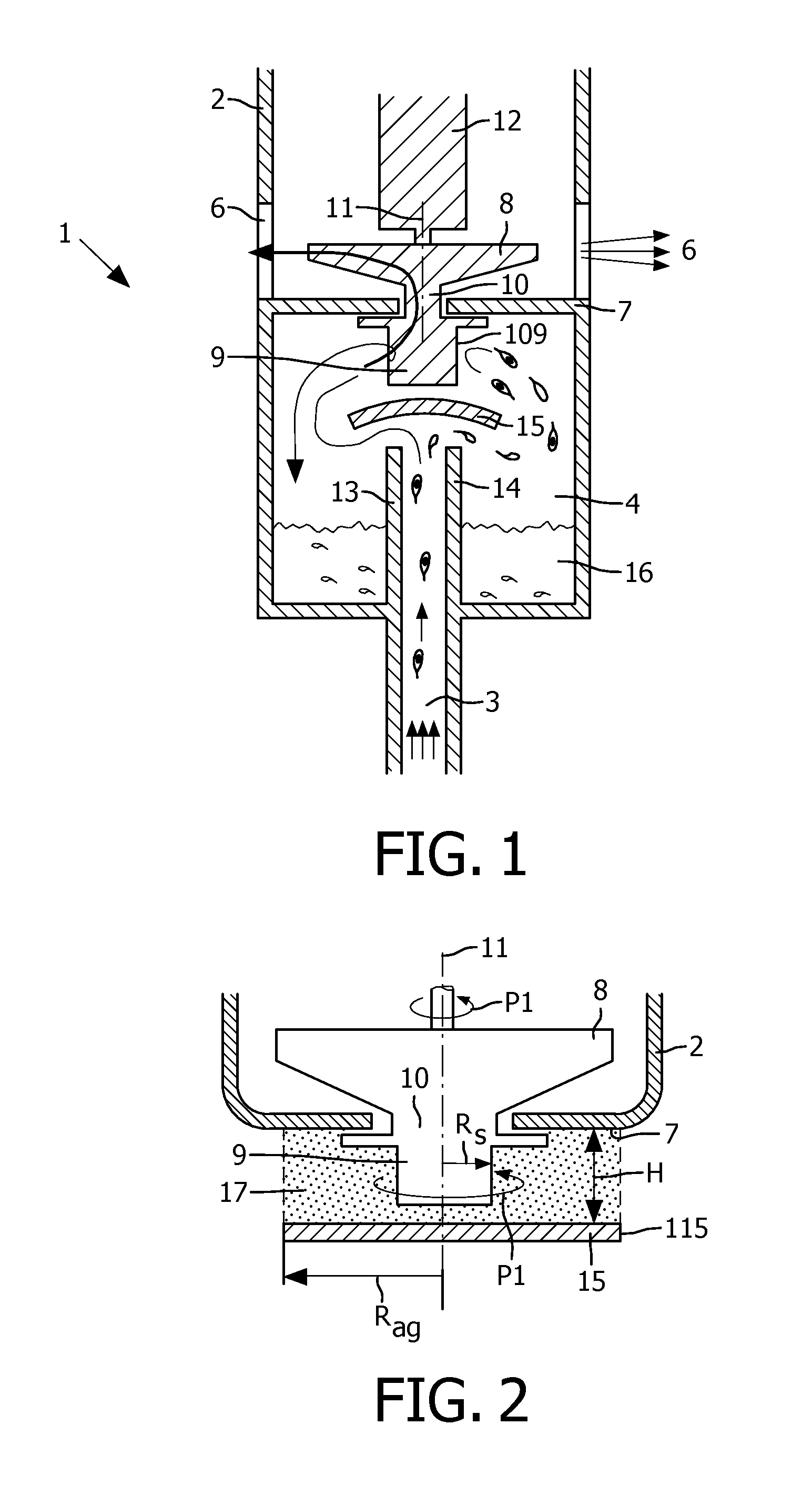
[0043]FIGS. 1-6B show different views of an embodiment of a vacuum cleaner 1 according to the invention. The vacuum cleaner 1 comprises a housing 2 provided with an air inlet opening 3, a first chamber 4, a second chamber 5 and air outlet openings 6. The air inlet opening 3 is located at the bottom of the first chamber 4, whilst air outlet openings 6 are located in a wall of the second chamber 5. Between the first and second chambers 4, 5 a wall 7 is located. The vacuum cleaner 1 is also provided with a vacuum fan 8 located in the second chamber 5 and a centrifugal fan 9 located in the first chamber 4. The vacuum fan 8 and the centrifugal fan 9 are connected to each other by means of a hollow tube 10 extending through the wall 7. The vacuum fan 8 and the centrifugal fan 9 are rotatable together about the rotating axis 11 by means of a motor 12. Air will enter the centrifugal fan 9 through air entrance openings 109 and leave the vacuum fan 8 near the air outlet openings 6. The motor ...


PUM

PropertyMeasurementUnit
sizeaaaaaaaaaa
angleaaaaaaaaaa
diameteraaaaaaaaaa

Abstract

A vacuum cleaner (1, 21, 31) comprises an air inlet opening (3), an air outlet opening (6) and a rotatable separator (9) for separating air and airborne particles. The separator (9) comprises at least one air entrance opening (109) located between the air inlet opening (3) and the air outlet opening (6). The vacuum cleaner (1, 21, 31) is provided with air-guide means (15, 22, 37) for guiding at least part of the air towards the separator (9). In use, the air-guide means (15, 22, 37) provides an at least partially closed boundary in axial direction for a column of rotating air (17) around the separator (9). The minimum distance (Rag) of an edge (115, 122) of the air-guide means (15, 22, 37) to the rotating axis (11) of the separator (9) is larger than a distance (Rs) of the air entrance opening (109) of the separator (9) to the rotating axis (11) of the separator (9).

Description

FIELD OF THE INVENTION[0001]The invention relates to a vacuum cleaner comprising an air inlet opening, an air outlet opening, a chamber and a rotatable separator for separating air and airborne particles, which separator comprises at least one air entrance opening located between the air inlet opening and the air outlet opening.BACKGROUND OF THE INVENTION[0002]By such a vacuum cleaner which is known from international patent publication WO 92 / 03210 A1, air polluted with airborne particles, like liquid, dust and dirt is being moved by means of vacuum towards the separator. When rotating the separator, centrifugal forces are exerted on the airborne particles due to which the airborne particles are being moved away from the separator, whilst the cleaned air flows through the separator towards the air outlet opening. Relatively heavy particles will be separated from the air at a relatively low rotational speed of the separator. However, to be able to remove relatively light particles as...

Claims


Application Information

Patent Timeline
Patent Type & Authority Patents(United States)
IPC IPC(8): A47L9/16
CPCA47L9/0072A47L7/0028A47L9/102A47L7/0023
Inventor VAN DER KOOI, JOHANNES TSEARDVOORHORST, FOKKE ROELOFDE WIT, BASTIANN JOHANNESBOERSMA, JOLDERT MARIA
Owner VERSUNI HLDG BV
Why Eureka
Try Eureka