
Tire

a technology of tires and tyres, applied in the field of tires, can solve the problems of road noise relayed and internal noise, and achieve the effect of reducing internal noise and external nois

Inactive Publication Date: 2014-04-15
BRIDGESTONE CORP
View PDF14 Cites 0 Cited by
  • Summary
  • Abstract
  • Description
  • Claims
  • Application Information

AI Technical Summary

Benefits of technology

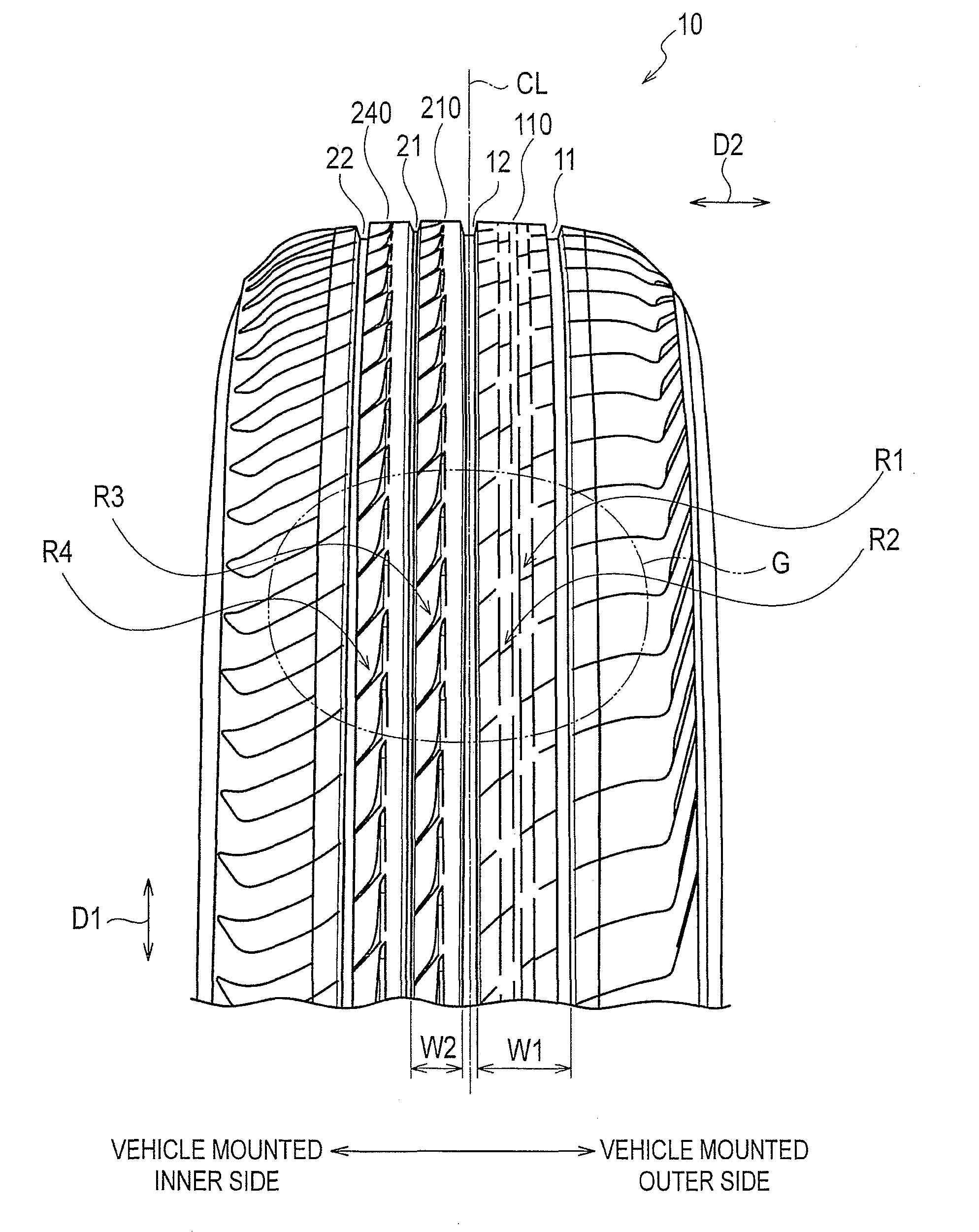
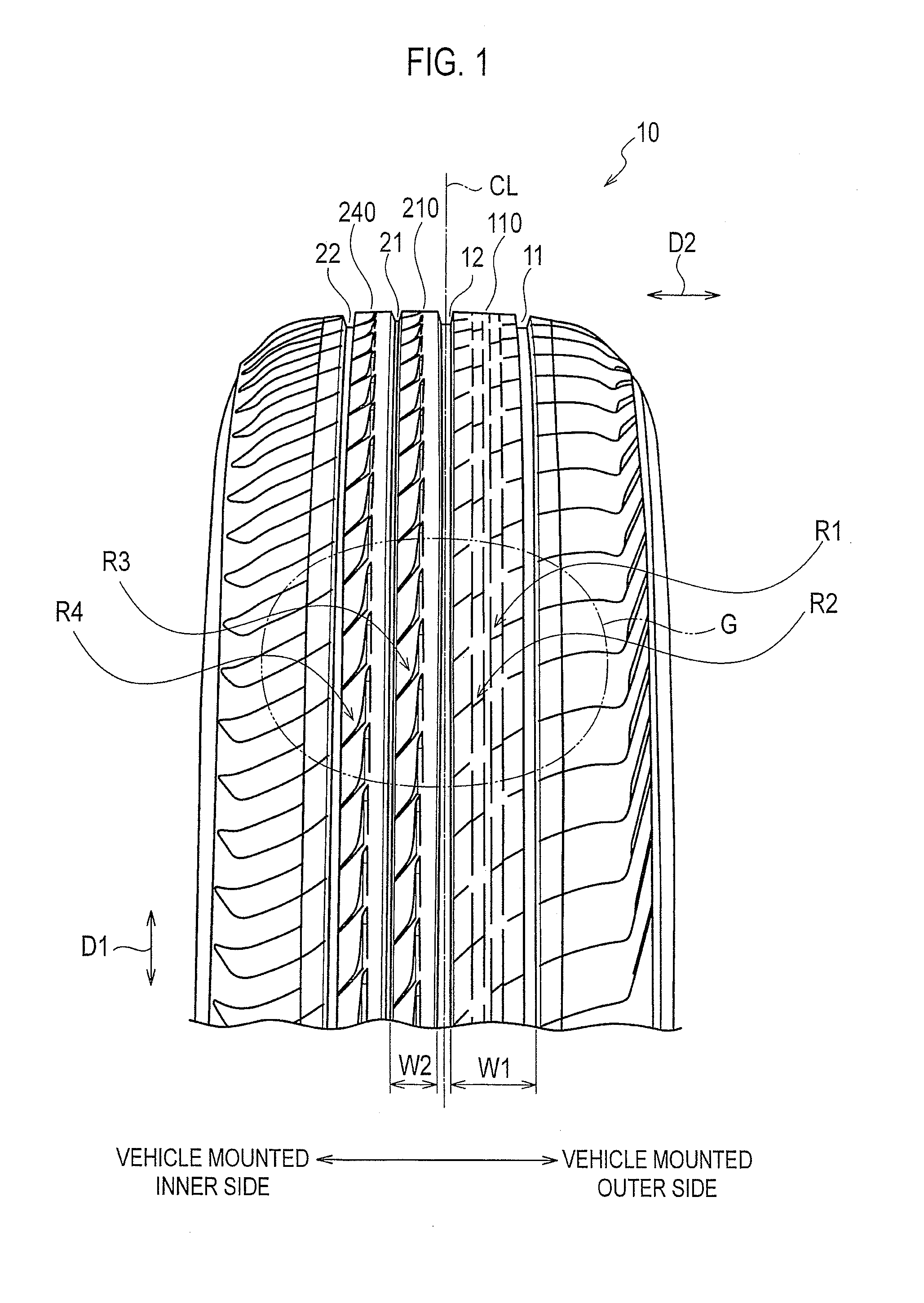
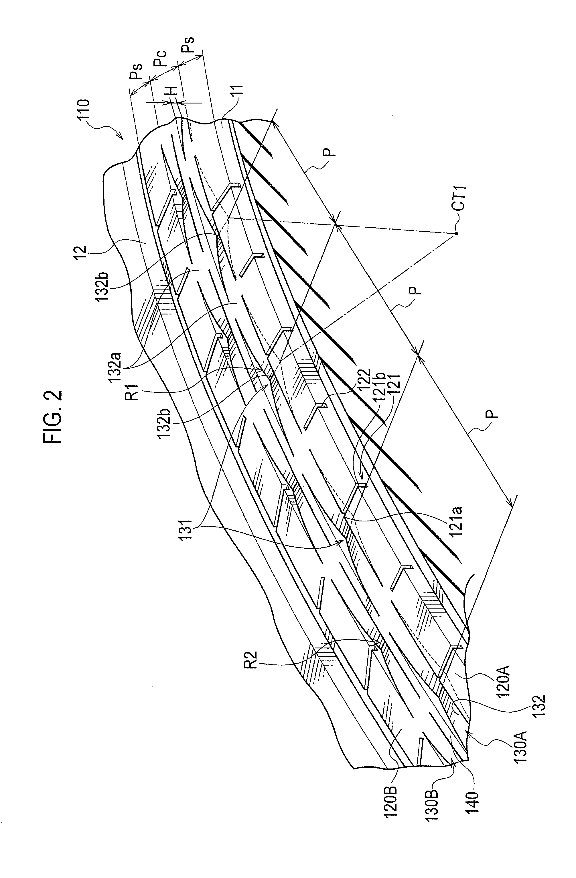
The present invention provides a tire that can effectively reduce both internal noise, such as road noise, and external noise, such as passage noise caused by air column tube resonance sound. This is achieved by using resonators that form a fixed space when making contact with the road surface, resulting in a lower block stiffness on the rib-like land portion where the second resonators are located, which reduces road noise. Additionally, the use of second resonators on the inner side of the tire, close to the suspension and axle shaft, suppresses road noise generated from this section. Overall, the tire can manage a high-level reduction of both internal and external noise.

Problems solved by technology

Also, road noise relayed by such as the suspension or the body and propagated in the car, becomes internal noise.

Method used


Image

  • Tire
  • Tire
  • Tire

Examples


first modification

(3.1) First Modification

[0064]FIG. 7 is a partial front view of the tire according to a first modification of the embodiment of the present invention. Specifically, FIG. 7 is a front view of the contact surface G2 according to the first modification of the embodiment of the present invention. FIG. 8 is a partial perspective view of the rib-like land portion 210 and the rib-like land portion 240 according to the first modification of the embodiment of the present invention.

[0065]As illustrated in FIG. 7, on the rib-like land portion 210 and the rib-like land portion 240, side-branch resonators are provided. Specifically, on the rib-like land portion 210 and the rib-like land portion 240, second resonators R5, R6, R7, R8, R9, and R10, which are recessed inward in the tire radial direction and which each form a predetermined space when the rib-like land portion 210 and the rib-like land portion 240 make contact with the road surface RS, are provided. The second resonators R5, R6, R7, R...

second modification

(3.2) Second Modification

[0069]FIG. 9 is a partial front view of the tire according to a second modification of the embodiment of the present invention. Specifically, FIG. 9 is a front view of a contact surface G3 according to the second modification of the embodiment of the present invention. FIG. 10 is a partial perspective view of the rib-like land portion 110 according to the second modification of the embodiment of the present invention.

[0070]As illustrated in FIG. 9, on the rib-like land portion 110, first resonators R11, R12, and R13 that consist of side-branch resonators in a single row along the tire circumferential direction are provided. Although in the embodiment mentioned above, the first resonators R1 and the first resonators R2 are provided in two rows along the tire circumferential direction, the present invention is not limited to this. Specifically, on the rib-like land portion 110, the first resonators R11, R12, and R13 which are recessed inward in the tire radial...

third modification

(3.3) Third Modification

[0071]FIG. 11 is a partial front view of the tire according to a third modification of the embodiment of the present invention. Specifically, FIG. 11 is a front view of a contact surface G4 according to the third modification of the embodiment of the present invention.

[0072]As illustrated in FIG. 11, on the rib-like land portion110, the rib-like land portion 210, and the rib-like land portion 240, second resonators R5, R6, R7, R8, R9, and R10, and first resonators R11, R12, and R13, which are side-branch resonators, are provided.


PUM


Abstract

A pneumatic tire (10) provided with: a rib-like land portion (110), a rib-like land portion (210), and a rib-like land portion (240) which are divided by circumferential grooves (11, 12, 21, 22) extending in the circumferential direction of the tire; and resonators which are recessed inward in the radial direction of the tire, which each form a predetermined space when the rib-like land portion (110) makes contact with the road surface, and which communicate with circumferential grooves. The resonators include first resonators which are provided in the circumferential direction of the tire, and also include second resonators which are, when the tire is mounted on a vehicle, located further toward the inboard side than the first resonators and are arranged in the circumferential direction of the tire. The number of the second resonators is greater than the number of the first resonators.

Description

CROSS REFERENCE TO RELATED APPLICATIONS[0001]This application is a National Stage of International Application No. PCT / JP2009 / 006363 filed Nov. 25, 2009, claiming priority based on Japanese Patent Application No. 2009-185275, filed Aug. 7, 2009, the contents of all of which are incorporated herein by reference in their entirety.TECHNICAL FIELD[0002]The present invention relates to a tire provided with resonators which are recessed inward in the tire radial direction, which each form a predetermined space when the rib-like land portion makes contact with the road surface, and which communicate with circumferential grooves.BACKGROUND ART[0003]Conventionally, in tires mounted on passenger vehicles, various methods have been materialized to reduce the air column tube resonance sound caused by spaces formed by circumferential grooves extending along the tire circumferential direction and the road surface. For example, there is known a tire in which side-branch resonators having longitudi...

Claims


Application Information

Patent Timeline
Patent Type & Authority Patents(United States)
IPC IPC(8): B60C11/04B60C11/12
CPCB60C11/1376B60C11/032B60C11/0306B60C11/0304B60C11/0318B60C2011/0381B60C2011/0341B60C5/00B60C11/00B60C11/04B60C11/13
Inventor KOJIMA, TAKAAKIKIWAKI, YUKIHIRO
Owner BRIDGESTONE CORP
Learn More