Display device with touch sensor, control system and control method thereof

a technology of touch sensor and display monitor, which is applied in the direction of instruments, computing, electric digital data processing, etc., can solve the problems of individual differences generated by external noise influences, deterioration of accuracy of position detection by touch sensor, and change in the distance between the touch panel and the casing, so as to reduce the external noise contained in the detection signal displayed on the display monitor

Inactive Publication Date: 2014-08-21
NEC LCD TECH CORP
View PDF4 Cites 5 Cited by
  • Summary
  • Abstract
  • Description
  • Claims
  • Application Information

AI Technical Summary

Benefits of technology

[0014]The control method according to still another exemplary aspect of the invention uses the control system of the present invention, and the control method includes: adjusting the distance between the display panel and the touch sensor by operating the control unit in such a manner that an external noise contained in the detection signal displayed on the display monitor is reduced.

Problems solved by technology

The display device provided with the capacitance type touch sensor has such an issue that a lot of noises are mixed into detection signals of the touch sensor since the touch sensor placed adjacent to a display panel is influenced by the noises generated from the display panel so that the accuracy of the position detection by the touch sensor becomes deteriorated.
Note, however, that the change in the distance between the touch panel and the casing with this technique is generated by applying a pressure on the touch panel.
However, in the state of the display device with the touch sensor in which the touch sensor and the display device are combined, there are individual differences generated in the influences of the external noises in the touch sensor due to variations in the structural members and assembling tolerance.
Thus, when the display device with the touch sensor is mounted into an electronic apparatus, it is not possible with the techniques described in Patent Documents 1 to 3 to perform adjustment even when the optimum values for the external noise vary for each device since those are being mounted into the electronic apparatuses.
Note that the external noise means an electric noise generated by the electronic apparatus itself to which the display device with the touch sensor is mounted in addition to an electric noise generated by the display panel.

Method used


Image

  • Display device with touch sensor, control system and control method thereof
  • Display device with touch sensor, control system and control method thereof
  • Display device with touch sensor, control system and control method thereof

Examples


Embodiment Construction

[0032]Hereinafter, modes for carrying out the present invention (referred to as “exemplary embodiments” hereinafter) will be described by referring to the accompanying drawings. In this Specification and the drawings, same reference numerals are used for substantially the same structural elements. The shapes in the drawings are illustrated to be easily comprehended by those skilled in the art, so that the dimensions and ratios thereof do not necessarily correspond to actual ones.

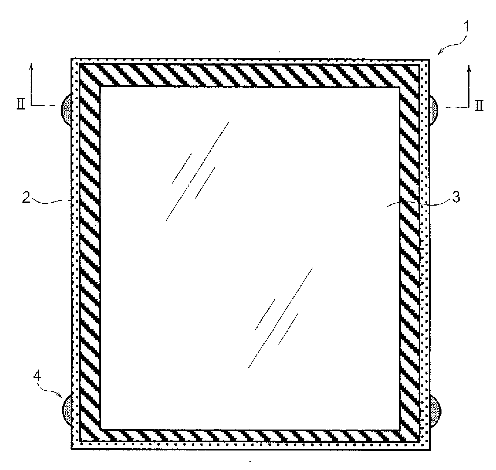
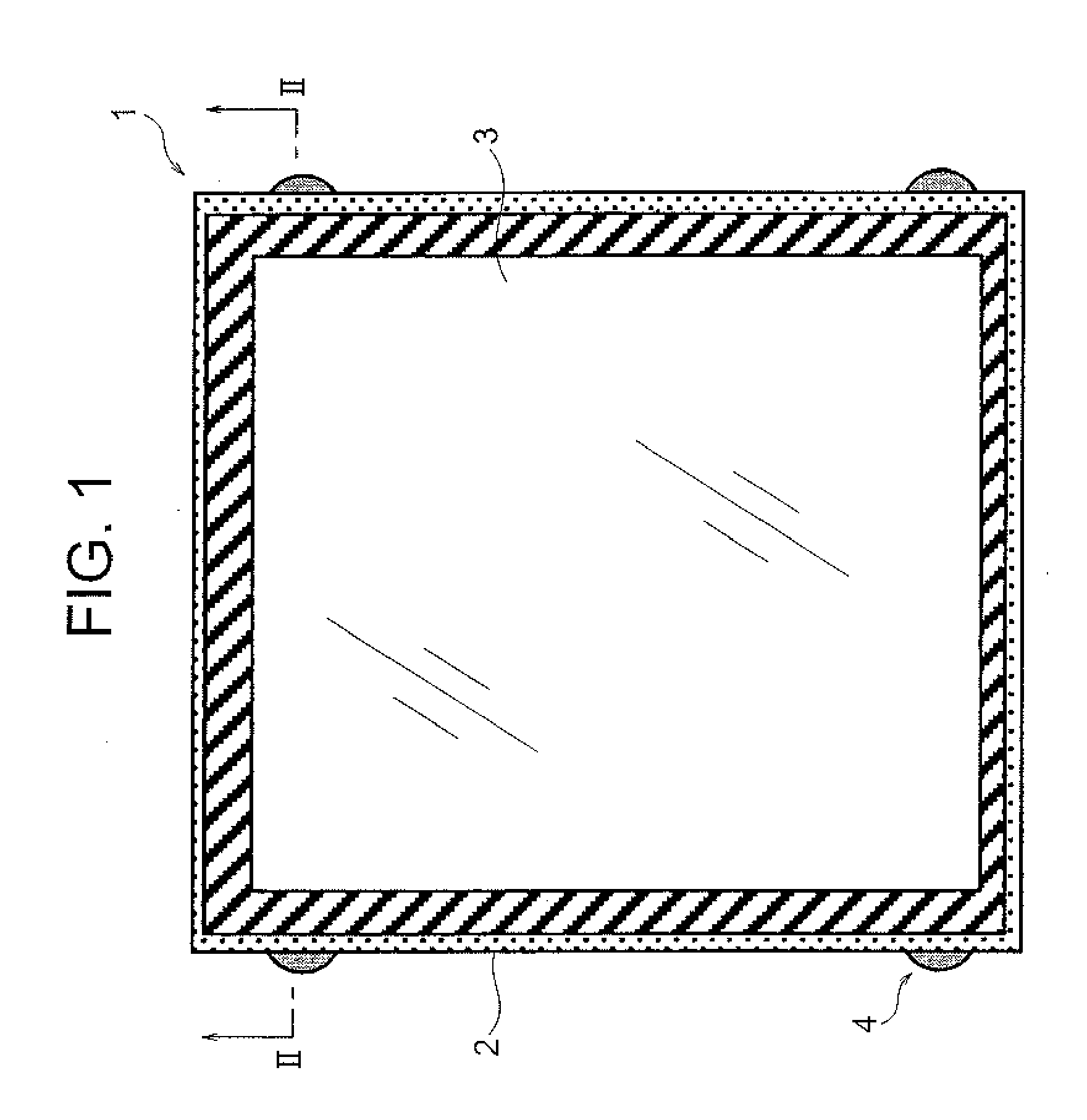
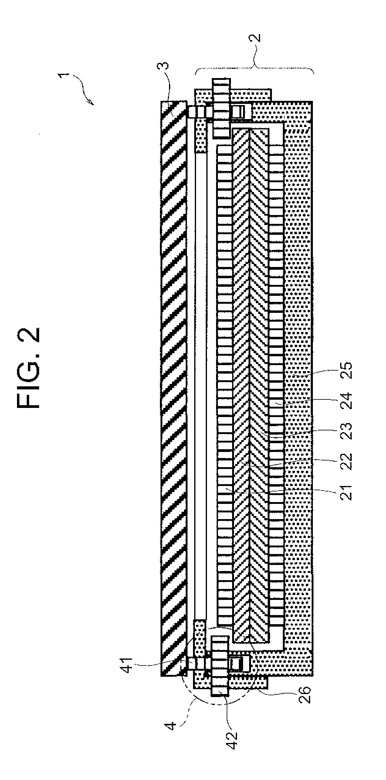
[0033]FIG. 1 is a plan view showing a display device with a touch sensor according to a first exemplary embodiment. FIG. 2 is a sectional view taken along a line II-II of FIG. 1. FIG. 3 is an enlarged sectional view of the touch sensor shown in FIG. 2. FIGS. 4A and 4B show enlarged sectional views of a distance variable mechanism shown in FIG. 2, in which FIG. 4A is a case where the distance between the touch sensor and the display panel is increased and FIG. 4B is a case where the distance between the touch...


PUM


Abstract

A display device with a touch sensor and the like, capable of adjusting the external noise even in a state where the touch sensor is being placed on a display panel or a state where the display device with the touch sensor is being mounted into an electronic apparatus, includes a display panel, a capacitance type touch sensor provided by being superimposed on the display panel, and a distance variable mechanism which changes the distance between the touch sensor and the display panel.

Description

CROSS-REFERENCE TO RELATED APPLICATION[0001]This application is based upon and claims the benefit of priority from Japanese patent application No. 2013-027464, filed on Feb. 15, 2013, the disclosure of which is incorporated herein in its entirety by reference.BACKGROUND OF THE INVENTION[0002]1. Field of the Invention[0003]The present invention relates to a display device with a touch sensor, which is a display device provided with a capacitance type touch sensor, and to a control system as well as a control method thereof.[0004]2. Description of the Related Art[0005]The display device provided with the capacitance type touch sensor has such an issue that a lot of noises are mixed into detection signals of the touch sensor since the touch sensor placed adjacent to a display panel is influenced by the noises generated from the display panel so that the accuracy of the position detection by the touch sensor becomes deteriorated.[0006]For that, Japanese Unexamined Patent Publication 201...

Claims


Application Information

Patent Timeline
Patent Type & Authority Applications(United States)
IPC IPC(8): G06F3/044
CPCG06F3/044G06F2203/04107G06F3/0445
Inventor MORISHITA, SHIZUO
Owner NEC LCD TECH CORP
Why Eureka
Try Eureka