DC/DC converter and television using same

a converter and television technology, applied in the field of dc/dc converters, can solve the problems of reducing the comparison voltage differential, preventing ripple mode voltage regulation, and preventing the reduction of so as to reduce the noise resistance properties caused by external noise and increase the on-duty ratio

Active Publication Date: 2014-09-09
ROHM CO LTD
View PDF24 Cites 7 Cited by
  • Summary
  • Abstract
  • Description
  • Claims
  • Application Information

AI Technical Summary

Benefits of technology

[0063]The technical field of the DC / DC converter according to the present invention is roughly in common with that of the fixed ON time control DC / DC converters disclosed in patent documents 1 through 5. The DC / DC converter according to the present invention provides a DC / DC converter enabling the problems with noise resistance properties discussed with reference to FIGS. 3 and 5 to be improved.
[0066]The present invention is configured so as to increase the ON duty ratio as the ON voltage generated by the ON resistance of the high-side transistor, i.e., the switching element, increases, enabling defects such as shifts in the operating point of the DC / DC converter or variations in operating frequency to be eliminated, and reduction of noise resistance properties to be prevented. Another invention of the present invention is configured so that a feedback resistor for determining an output voltage is built into an integrated circuit, enabling defects such as a reduction in noise resistance properties caused by external noise to be minimized.

Problems solved by technology

According to paragraph 0011, it is possible to minimize noise and reduce variation in load voltage by reducing the ripple, but this impedes ripple mode voltage regulation.
Reducing ripple size also decreases the comparison voltage differential, greatly impeding swift and accurate comparison.
Such variation in switching frequency forebodes difficulties in preventing noise generated by switching.
Patent document 5 also points out that when a plurality of DC / DC converters are operated, a problem arises in that electromagnetic interference (EMI) noise is generated by the mutual interference among the plurality of switching frequencies arising from the differences in switching frequency between the DC / DC converters.
This is because, while it is possible to provide a band-pass filter that dampens the frequency components when the frequency is constant, such a measure is not possible when the operating frequency of the DC / DC converter 30 varies at random.
However, it is not preferable for ESR and ripple voltage amplitude to be increased, as this reduces noise resistance properties as well as load voltage properties.

Method used


Image

  • DC/DC converter and television using same
  • DC/DC converter and television using same
  • DC/DC converter and television using same

Examples


first embodiment

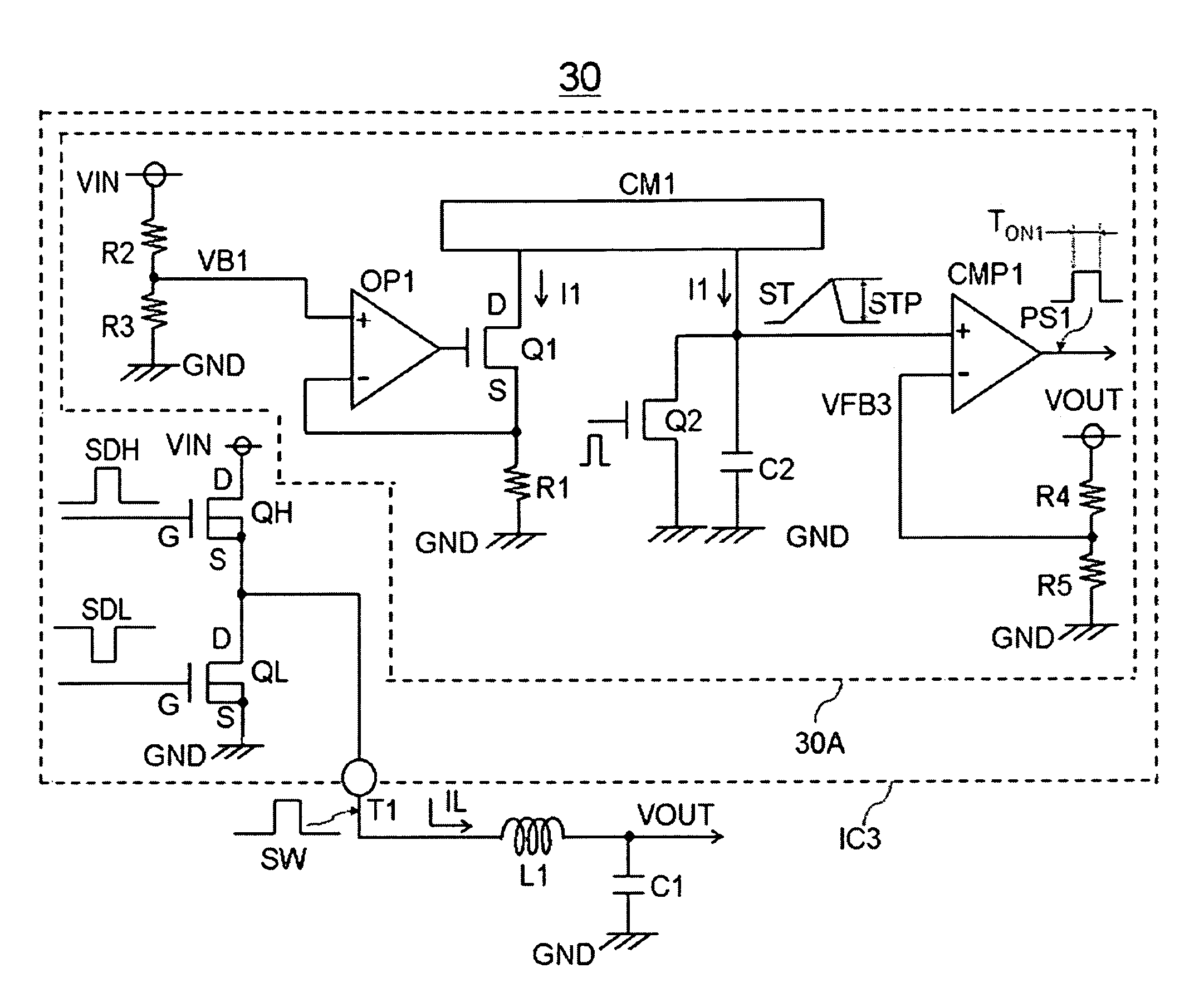
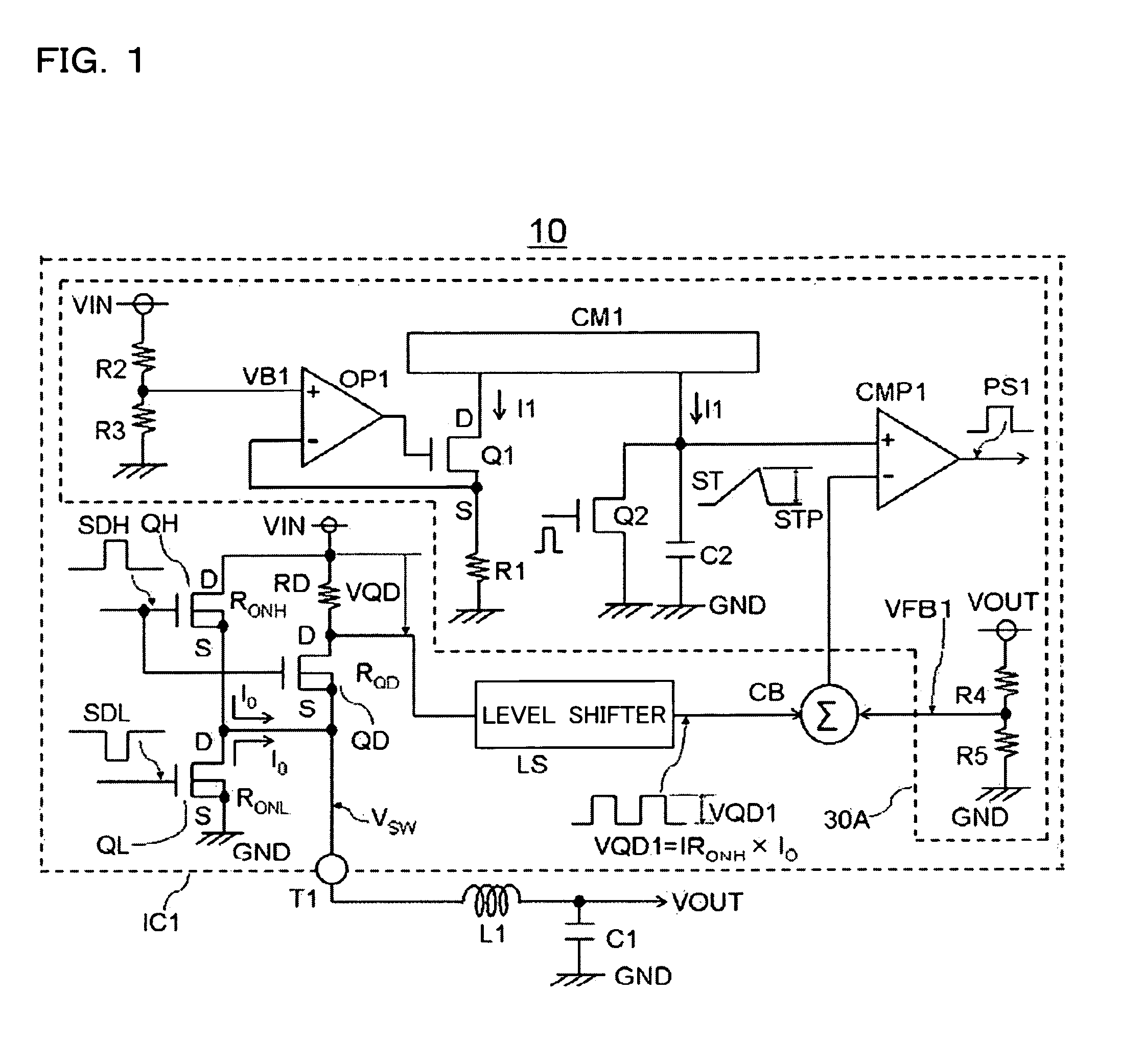
[0079]FIG. 1 depicts a DC / DC converter according to a first embodiment of the present invention. A DC / DC converter 10 utilizes the many circuit components shown in FIG. 3; description of the operation of these circuit components shall be omitted. A high-side transistor QH corresponds to the switching element spoken of in the context of the present invention, and a low-side transistor QL functions as a synchronous rectification element.

[0080]Briefly put, the first embodiment of the present invention illustrated in FIG. 1 is characterized in having an input voltage VIN, an external terminal T1 that converts the input voltage VIN and outputs an output voltage VOUT, an inductor L1 connected to the external terminal T1, a high-side transistor (switching element) QH having a first primary electrode D connected to the input voltage VIN and a second primary electrode S connected to the inductor L1 so as to supply energy to the inductor L1, an output capacitor C1 that smoothes the energy acc...

second embodiment

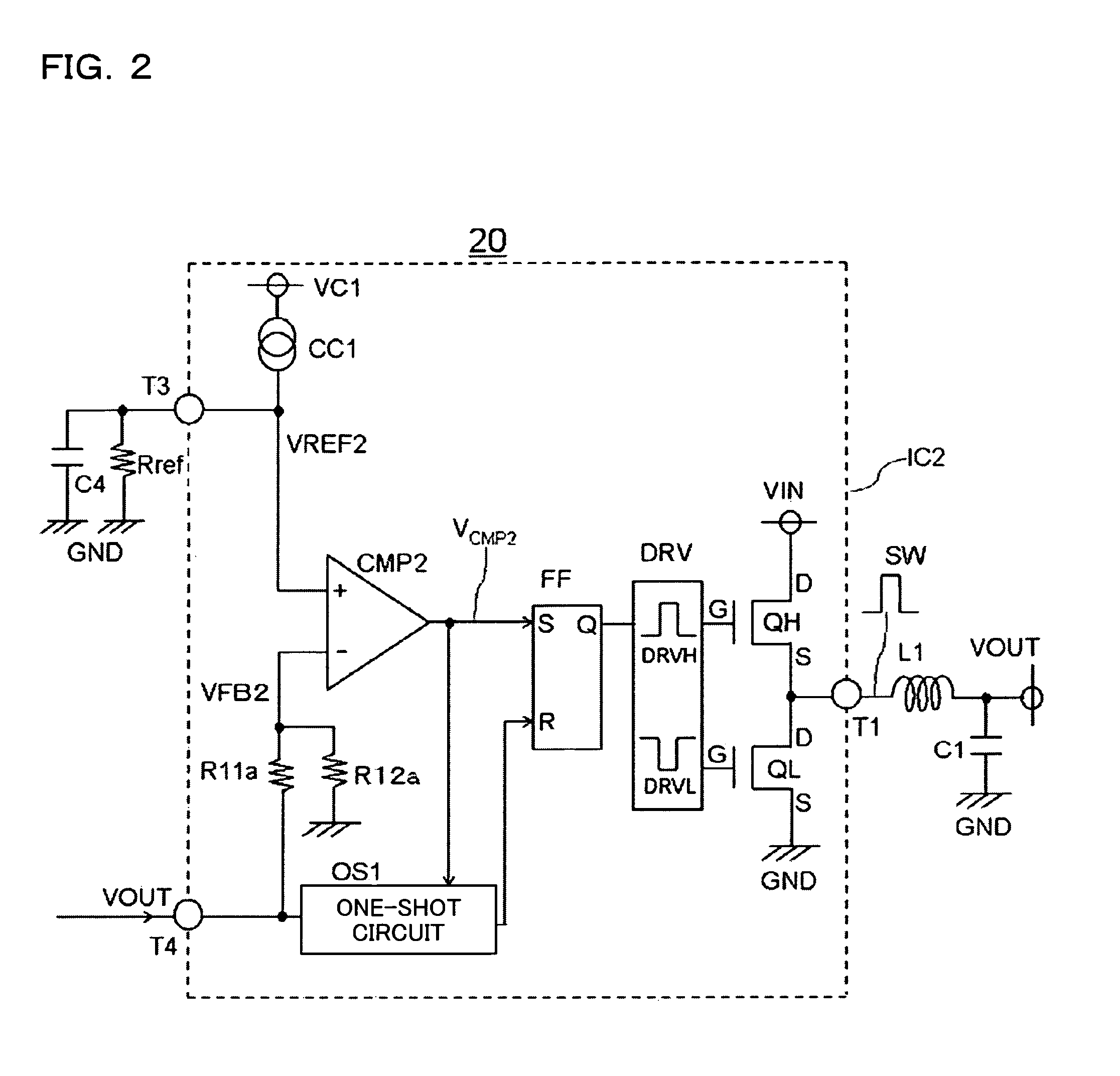
[0105]FIG. 2 illustrates a second embodiment of the present invention. This embodiment shares improvement in noise resistance properties in common with the first embodiment.

[0106]An integrated circuit IC2 represents the primary circuit of a DC / DC converter 20. The integrated circuit IC2 can utilize the many circuit components included in the integrated circuit IC5 shown in FIG. 5; description of the operation of these shall be omitted. Here, the points of difference between FIG. 2 and FIG. 5 will be described. A first point of difference is that the integrated circuit IC2 does not include an external terminal T2. It is convenient to leave out the external terminal T2 when constructing the integrated circuit IC2. This is because miniaturization of the package containing the integrated circuit IC2 is thus made possible. When a different circuit component is used in place of the eliminated external terminal T2, the circuit functions built into the integrated circuit IC2 can be increase...


PUM


Abstract

A DC / DC converter 10 has a high-side transistor QH as a switching element and a low-side transistor QL as a synchronous rectifier element. A first primary electrode D and secondary primary electrode S of the high-side transistor QH are connected to an input voltage VIN and an external terminal T1, respectively. A detection transistor QD is provided in a row with the high-side transistor QH, and the ON voltage of the high-side transistor QH when ON is output as detection voltage VQD from the detection transistor QD. The output detection voltage VQD is added to a feedback voltage VFB1 by an adder CB, and inputted to a comparator CMP1. The ON period of a one-shot pulse PS1 outputted from the comparator CMP1 is regulated so as to be in direct proportion to the sum of the detection voltage VQD and the feedback voltage VFB1.

Description

CROSS-REFERENCE TO RELATED APPLICATIONS[0001]This application is based upon and claims the benefit of priority from the corresponding following Japanese Patent Applications, the entire contents of which are incorporated herein by reference.[0002](1) Japanese Patent Application No. 2011-048503 (filed Mar. 7, 2011)[0003](2) Japanese Patent Application No. 2012-021852 (filed Feb. 3, 2012)BACKGROUND OF THE INVENTION[0004]1. Field of the Invention[0005]The present invention relates to a DC / DC converter, and in particular to a DC / DC converter using fixed ON time control.[0006]2. Description of Related Art[0007]DC / DC converters are widely adopted for use in power sources for liquid crystal televisions, digital versatile disc (DVD) players, Blu-ray Disc players, plasma display panels (PDPs), and the like.[0008]Patent document 1 (Unexamined Japanese Patent Application Publication No. 2008-29159) provides a DC / DC converter performing fixed ON time pulse frequency modulation (PFM) control, tha...

Claims


Application Information

Patent Timeline
Patent Type & Authority Patents(United States)
IPC IPC(8): H04N5/63
CPCH02M3/156H02M2001/0022H04N5/63H02M1/0022
Inventor MURAKAMI, KAZUHIRO
Owner ROHM CO LTD
Why Eureka
Try Eureka