
Wellhead tree pressure compensating device

a compensating device and wellhead technology, applied in the direction of drilling machines and methods, borehole/well accessories, underwater drilling, etc., can solve the problems of affecting the integrity of the crown plug, the fluid may be relatively cold, etc., and achieve the effect of reducing the pressure increas

Inactive Publication Date: 2014-04-15
VETCO GRAY
View PDF47 Cites 0 Cited by
  • Summary
  • Abstract
  • Description
  • Claims
  • Application Information

AI Technical Summary

Benefits of technology

The device effectively mitigates pressure increases from thermal expansion, preventing damage to the crown plugs by allowing elastic deformation of the plates, which returns to its original state when the fluid cools, maintaining stable pressure within the wellhead.

Problems solved by technology

The fluid may be relatively cold when it is trapped because the subsea temperature is relatively cold.
As the fluid trapped between the crown plugs heats up and is restricted from expanding, the trapped fluid pressure can potentially increase above the working pressure of the crown plugs and, thus, damage the integrity of the crown plugs.

Method used


Image

  • Wellhead tree pressure compensating device
  • Wellhead tree pressure compensating device
  • Wellhead tree pressure compensating device

Examples


Embodiment Construction

[0017]The present invention will now be described more fully hereinafter with reference to the accompanying drawings which illustrate embodiments of the invention. This invention may, however, be embodied in many different forms and should not be construed as limited to the illustrated embodiments set forth herein. Rather, these embodiments are provided so that this disclosure will be thorough and complete, and will fully convey the scope of the invention to those skilled in the art. Like numbers refer to like elements throughout, and the prime notation, if used, indicates similar elements in alternative embodiments.

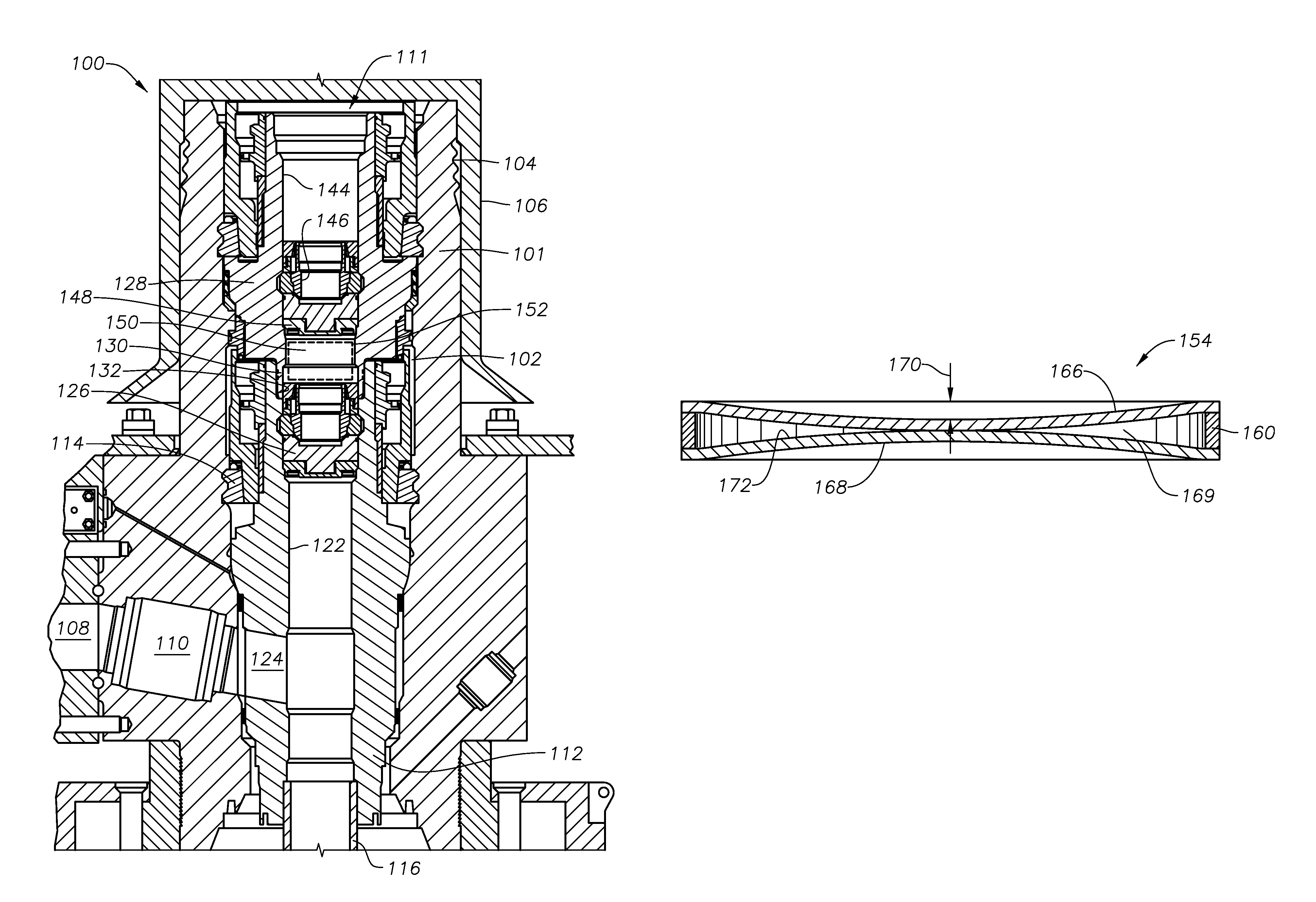
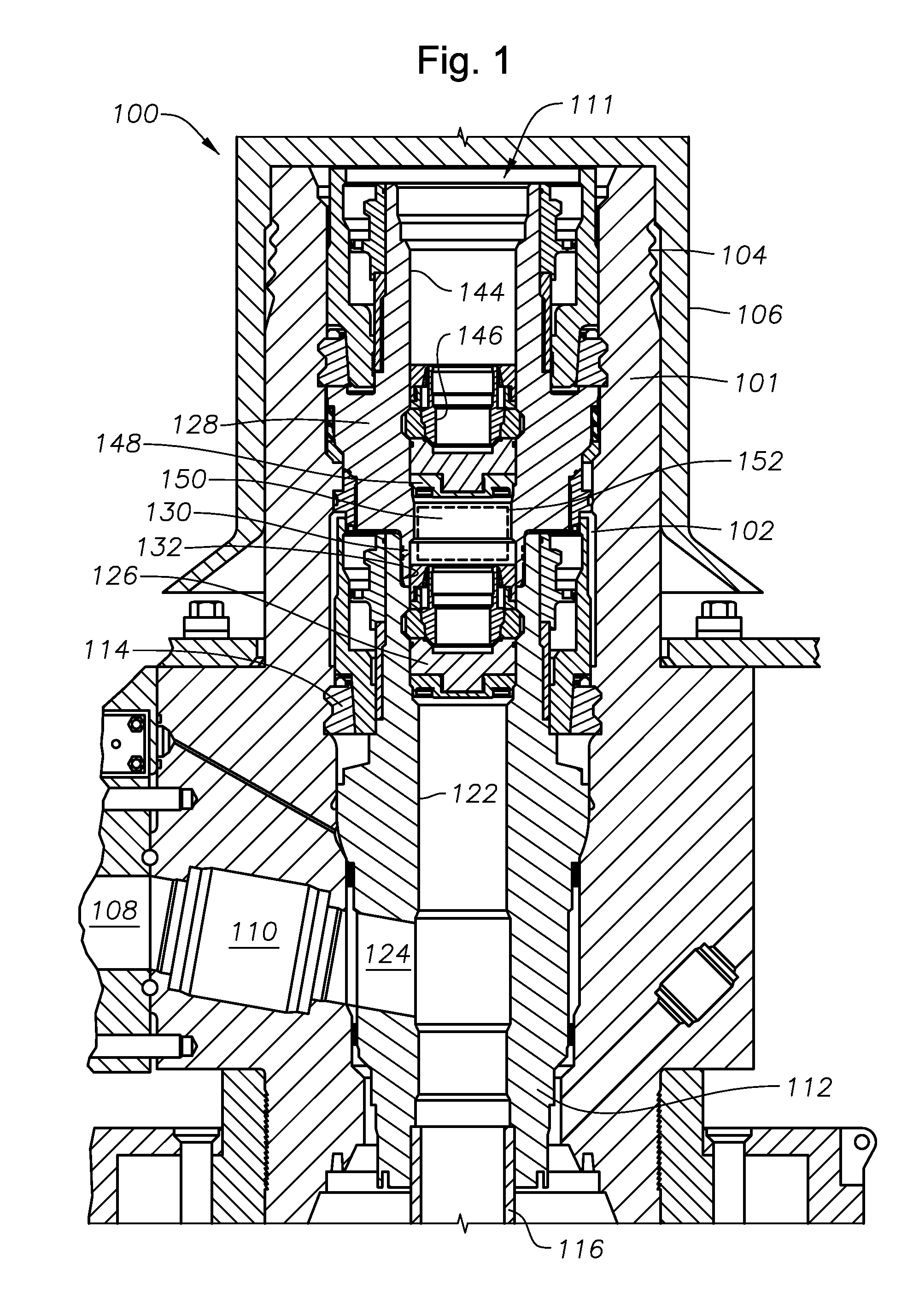
[0018]Referring to FIG. 1, Christmas tree 100 is of a type known as a horizontal tree. It has a tree block 101 with a vertical or axial tree bore 102 extending completely through it. A set of grooves 104 is located on the exterior near the upper end for connection to a drilling riser (not shown). A removable corrosion cover 106 fits over the upper end of tree 100. Tree 1...


PUM


Abstract

A pressure mitigating device is used to reduce pressure in a void within a wellhead housing. In one embodiment, the pressure mitigating device includes two plates that define a void between them. Increased pressure in the wellhead housing causes the plates to elastically displace towards each other. The plates contact each other, limiting the displacement prior to plastic deformation.

Description

BACKGROUND OF THE INVENTION[0001]1. Field of the Invention[0002]The present invention relates in general to a method and apparatus to mitigate trapped pressure in a wellhead and in particular to a compressible pressure limiting device for limiting pressure from a void typically located between two crown plugs in a wellhead tree system.[0003]2. Brief Description of Related Art[0004]A horizontal subsea tree has a production outlet extending generally horizontally, in relation to the wellbore, and a bore that is axially aligned with the wellbore. A tubing hanger lands in the horizontal tree and supports a string of tubing extending into the wellbore. The tubing hanger has a vertical passage and a lateral passage extending from the vertical passage and registering with the production outlet of the tree. In some installations an internal tree cap lands in the tree above the tubing hanger, the tree cap normally having a vertical passage that aligns with the vertical passage in the tubing ...

Claims


Application Information

Patent Timeline
Patent Type & Authority Patents(United States)
IPC IPC(8): E21B33/043E21B33/035E21B34/04E21B23/04E21B33/134
CPCE21B33/035E21B34/04E21B33/0353
Inventor URQUHART, ALEXANDERMUNRO, WILLIAM D.
Owner VETCO GRAY
Learn More