
Oil pump

a technology of oil pump and oil cylinder, which is applied in the direction of liquid fuel engines, rotary/oscillating piston pump components, machines/engines, etc., can solve the problems of increasing friction and cavitation, and achieve the effects of preventing rapid variation in the surface area of the cell moving over the first seal land, reducing friction and increasing pressur

Active Publication Date: 2016-04-12
YAMADA MANUFACTURING CO LTD
View PDF7 Cites 0 Cited by
  • Summary
  • Abstract
  • Description
  • Claims
  • Application Information

AI Technical Summary

Benefits of technology

The present invention provides an oil pump that can prevent an increase in friction, the occurrence of cavitation, and pumping loss. It does this by providing an escape portion that lets out a part of the starting end of the intake port forward in the rotor rotation direction. This results in a rapid increase in cell surface area, leading to a rapid pressure reduction when the cell communicates with the intake port, leading to an increase in friction and cavitation. The oil pump also prevents a reduction in efficiency by ensuring a balanced discharge of oil from the cell. In summary, the oil pump provides improved performance and stability during use.

Problems solved by technology

As a result, an increase in friction and cavitation occur.

Method used


Image

  • Oil pump
  • Oil pump
  • Oil pump

Examples


Embodiment Construction

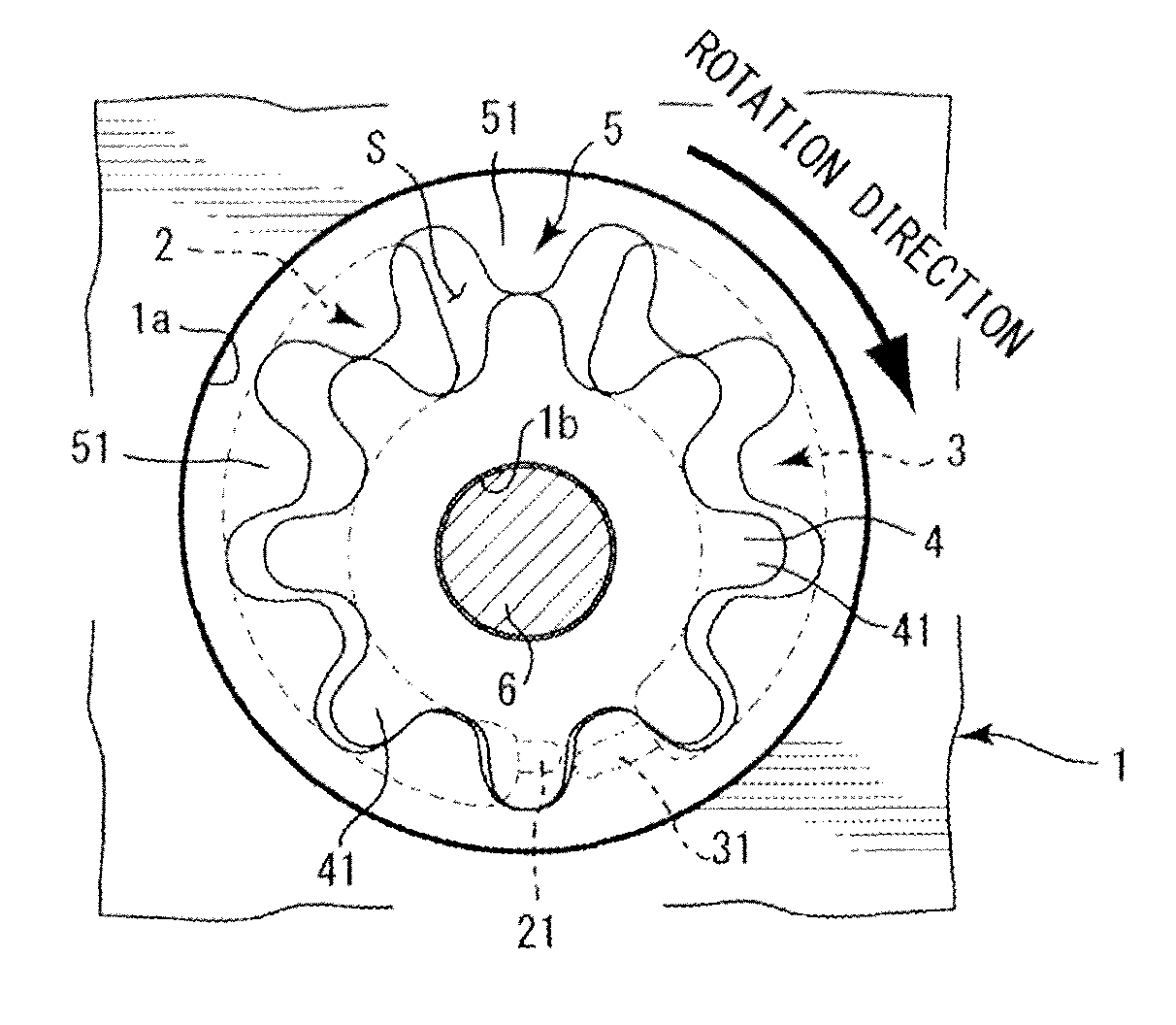
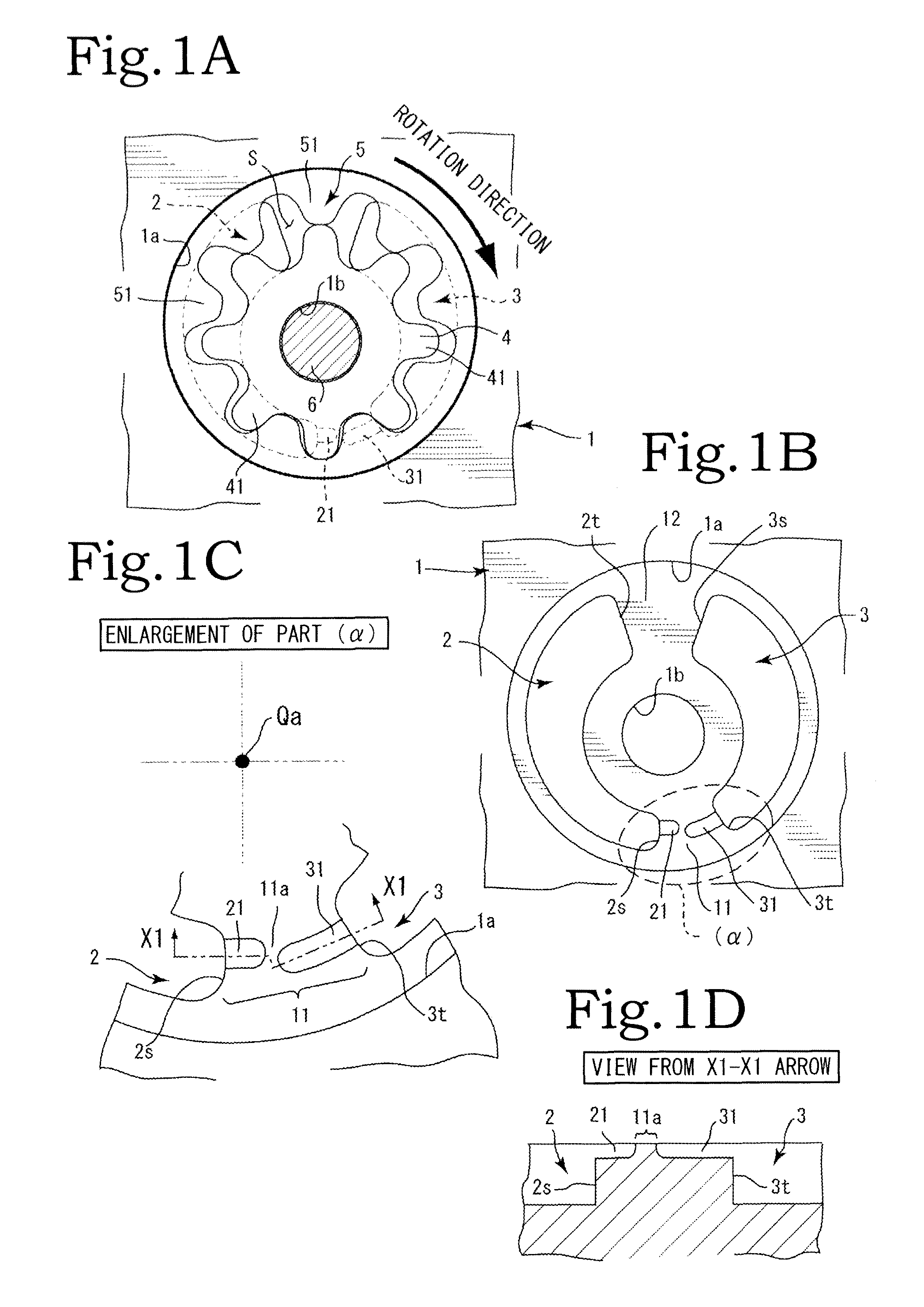
[0020]Embodiments of the present invention will be described below on the basis of the drawings. As shown in FIG. 1A, a housing 1, an inner rotor 4, and an outer rotor 5 serve as main constituent components of the present invention. In the present invention, the inner rotor 4 and the outer rotor 5 together constitute an internal gear pump.

[0021]The inner rotor 4 and the outer rotor 5, which has one more tooth than the inner rotor 4, are disposed eccentrically such that respective center positions thereof are offset, and housed in a rotor chamber 1a of the housing 1. In the inner rotor 4, a plurality of outer teeth 41 provided on an outer peripheral side mesh with a plurality of inner teeth 51 of the outer rotor 5. A tooth height of the outer teeth 41 provided on the inner rotor 4 may be set to be greater than a tooth height of the inner teeth 51 provided on the outer rotor 5.

[0022]The inner rotor 4 and the outer rotor 5 constitute an internal gear pump in which spaces (to be referre...


PUM


Abstract

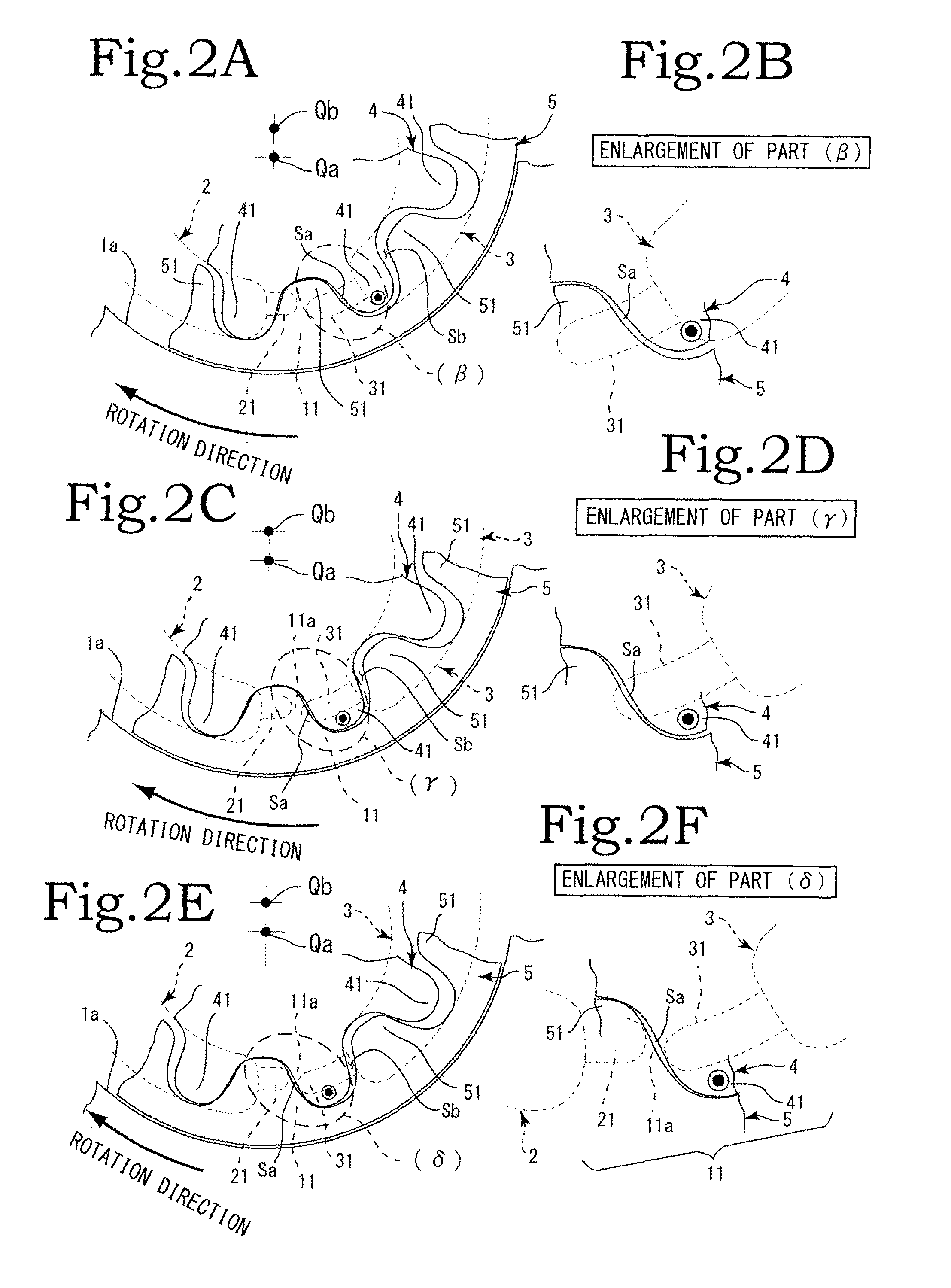
An oil pump includes: a rotor chamber; an outer rotor; and an inner rotor. A partition surface between a starting end side of the intake port and a terminal end side of the discharge port is set as a first seal land. An intake groove portion that projects from the starting end side of the intake port toward the terminal end side of the discharge port and a discharge groove portion that projects from the terminal end side of the discharge port toward the starting end side of the intake port are formed in positions which are located on the first seal land. The intake groove portion and the discharge groove portion are provided in intermediate tooth height direction positions of a meshing location between the inner rotor and the outer rotor.

Description

BACKGROUND OF THE INVENTION[0001]1. Field of the Invention[0002]The present invention relates to an oil pump capable of suppressing an increase in friction and the occurrence of cavitation and pumping loss.[0003]2. Description of the Related Art[0004]Japanese Patent Application Publication No. 2010-96011 is available as an internal gear pump according to the related art. In Japanese Patent Application Publication No. 2010-96011 (reference symbols provided in the description of Japanese Patent Application Publication No. 2010-96011 are used as is), a passage 11 is provided to extend forward in a rotor rotation direction from a terminal end of a discharge port 7, and fluid pressure is introduced through the passage 11 from the discharge port 7 into a pump chamber 10 that has moved to a position where a capacity thereof is minimized.[0005]A force for separating an inner rotor 4 from an outer rotor 3 is generated on an upper side of a part where the pump chamber 10 is confined by the fl...

Claims


Application Information

Patent Timeline
Patent Type & Authority Patents(United States)
IPC IPC(8): F01C1/00F04C2/10F04C18/00F04C15/00F04C2/08F03C4/00F03C2/00F04C2/00
CPCF04C2/088F04C2/103F04C15/0026F04C15/0049
Inventor FUJIKI, KENICHIIZUTSU, MASATO
Owner YAMADA MANUFACTURING CO LTD
Learn More