
Compensation of magnetic field components caused by a periodic motion of a cold head

Active Publication Date: 2021-05-06
KONINKLJIJKE PHILIPS NV
View PDF0 Cites 0 Cited by
  • Summary
  • Abstract
  • Description
  • Claims
  • Application Information

AI Technical Summary

Benefits of technology

The invention provides a method for compensating for periodic B0 modulations in a magnetic resonance imaging system caused by the movement of the cold head. This is achieved by cooling the main magnet of the system with the cold head, which exerts a repetitive motion. The method involves measuring the magnetic field and using calibration data to compensate for the cold head movement and improve the quality of the magnetic resonance images. The compensation signals can be generated once during set-up or replacement of the cold head and can be applied based on the trigger. This method simplifies the process of compensating for the cold head movement and improves the quality of the magnetic resonance images.

Problems solved by technology

Despite this shielding, the field modulation in the imaging volume is too big for some types of MR imaging scans.
Hence, the main magnet cannot be actively cooled during the acquisition of those MR imaging signals, which leads to a temperature increase in the cryogen.

Method used


Image

  • Compensation of magnetic field components caused by a periodic motion of a cold head
  • Compensation of magnetic field components caused by a periodic motion of a cold head
  • Compensation of magnetic field components caused by a periodic motion of a cold head

Examples


first embodiment

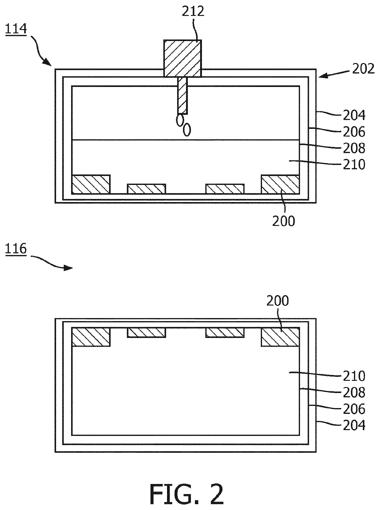
[0047]The cryogenic vessel 202 comprises three individual vessels 204, 206, 208, which are mounted spaced apart to achieve thermal isolation. The individual vessels 204, 206, 208 are mounted in a surrounding manner from an inner vessel 208 to an outer vessel 204. The inner vessel 208 is a 4K vessel, which contains liquid helium 210 as cryogen, a radiation shield 206, which is provided as an intermediate vessel surrounding the inner vessel 208, and an outer vessel 204, also referred to as 300K vessel, surrounding the radiation shield 206. The main magnet coils 200 of the superconductive main magnet 114 are located within the inner vessel 208 and mounted to a mounting structure, which is not shown in the figures. The individual vessels 204, 206, 208 are made of stainless steel and / or aluminum.

[0048]As can be further seen in FIG. 2, a cold head 212 is provided extending through the cryogenic vessel 202. According to the first embodiment, the main coils 200 of the main magnet 114 are i...

second embodiment

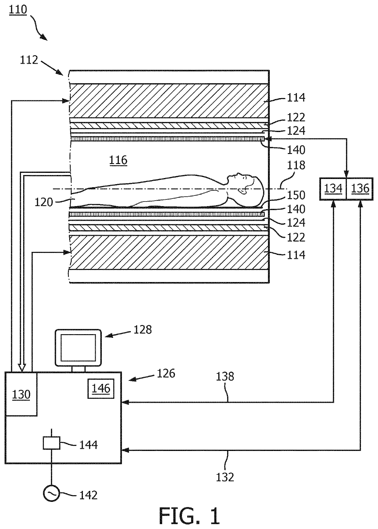
[0050]Also the MR imaging system 110 is connected to power mains 142 with a given mains frequency. A current sensor 144 is provided as measurement means in the control unit 126 and coupled to the power mains 142 to sense the mains current with the mains frequency. Furthermore, the control unit 126 comprises a data storage 146 for storing a compensation signal, as discussed later on.

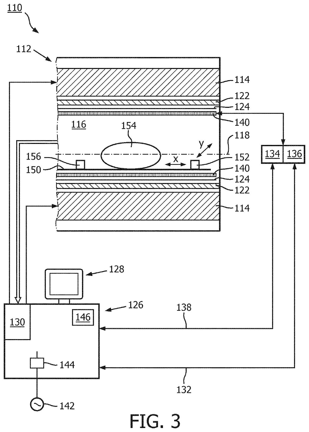
[0051]As can be further seen in FIG. 3, the MR imaging system 110 of the second embodiment comprises different types of measurement means 152, 156 for measuring a periodic occurrence spatial field components of the B-field based on a motion of the cold head 212 as a function of time. In particular, the measurement means 152, 156 comprise a MR probe 152 and a pick-up coil 156. The MR probe 152 as well as the pick-up coil 156 are placed on the patient support 150 within the examination space 116 of the MR imaging system 110. The pick-up coil 156 refers to a receive coil, which can sense a field in one dire...

third embodiment

[0056]As can be seen in FIG. 4, different sensor means 222, 226 for determining a periodic sensor signal with the frequency of the periodic B0 modulation are provided at the cold head 212 or the tubes 224. In particular, the sensor means 222, 226 comprise an accelerometer 222, which detects vibration of components of the MR imaging system 110 based on vibrations induced by the movement of the cold head 212. the accelerometer 222 is attached to the cold head 212. The sensor means 222, 226 further comprise a pressure sensor 226, which is provided along tubes 224. The pressure sensor 226 detects variations in the pressure within the tubes 224.

[0057]Furthermore, a microphone 220 is provided within the examination space 116 of the MR imaging system 110 as sensor means. The microphone 220 determines a sound or vibrations based on the cold head 212 movement. In an alternative embodiment, the sensor means 220, 222, 226 comprise other kinds of sensor like e.g. a magnetic sensor or an electr...


PUM


Abstract

The present invention provides a method for compensation of periodic B0 modulations from a periodic motion of a cold head (212) of a main magnet (114) of a magnetic resonance (MR) imaging system (110), whereby main windings (200) of the main magnet (114) are cooled to superconductivity by the cold head (212), which exerts a repetitive motion, the method comprising the steps of measuring a periodic occurrence of spatial field components of the B-field based on a motion of the cold head (212) as a function of time, performing a sensor measurement of a periodic, auxiliary parameter of the MR imaging system (110), which is not the periodic occurrence of spatial field components, synchronizing the periodic occurrence of spatial field components of the B-field with the measured periodic, auxiliary parameter of the MR imaging system (110), and triggering based on the measured periodic sensor measurement of the MR imaging system (110) a periodic application of compensation signals to compensate the periodic occurrence of spatial field components of the B-field based on a motion of the cold head (212). Furthermore, the present invention provides a MR imaging system (110) for providing an image representation of a region of interest (142) of a subject of interest (120) positioned in an examination space (116) of the MR imaging system (110), wherein the MR imaging system (110) is adapted to perform the above method.

Description

FIELD OF THE INVENTION[0001]The invention relates to the field of magnetic resonance (MR) examination systems, in particular to the field of superconductive magnets for MR examination systems, still more particular to the field of compensation of periodic B0 modulations from a periodic motion of a cold head of a main magnet of a magnetic resonance (MR) imaging system, whereby main windings of the main magnet are cooled to superconductivity by the cold head, which exerts a repetitive motion. Even more particular, the invention refers to the field of MR imaging systems for providing an image representation of a region of interest of a subject of interest positioned in an examination space of the MR imaging system.BACKGROUND OF THE INVENTION[0002]A magnetic resonance (MR) examination system comprises a main magnet with a cryogenic vessel, in which main magnet coils of the main magnet, which is a superconductive magnet, are mounted. The cryogenic vessel typically comprises two or three ...

Claims


Application Information

Patent Timeline
IPC IPC(8): G01R33/38G01R33/565G01R33/3815G01R33/3875
CPCG01R33/3804G01R33/3875G01R33/3815G01R33/56563G01R33/389
Inventor HAM, CORNELIS LEONARDUS GERARDUSVAN LIERE, FILIPS
Owner KONINKLJIJKE PHILIPS NV
Learn More