

Vehicle lift
a technology for lifting and lifting vehicles, applied in the field of lifting, can solve the problems of inability to adapt to the use of the lift, the lift is too wide, the lift is too expensive for general use, and the headroom of the lift is too large, so as to achieve the effect of convenient portability, convenient operation and convenient portability
- Summary
- Abstract
- Description
- Claims
- Application Information
AI Technical Summary
Benefits of technology
Problems solved by technology
Method used
Image

Examples
Embodiment Construction
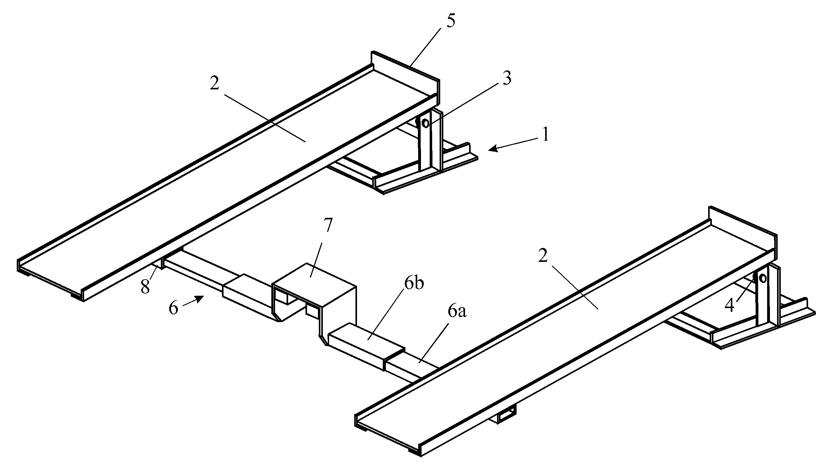
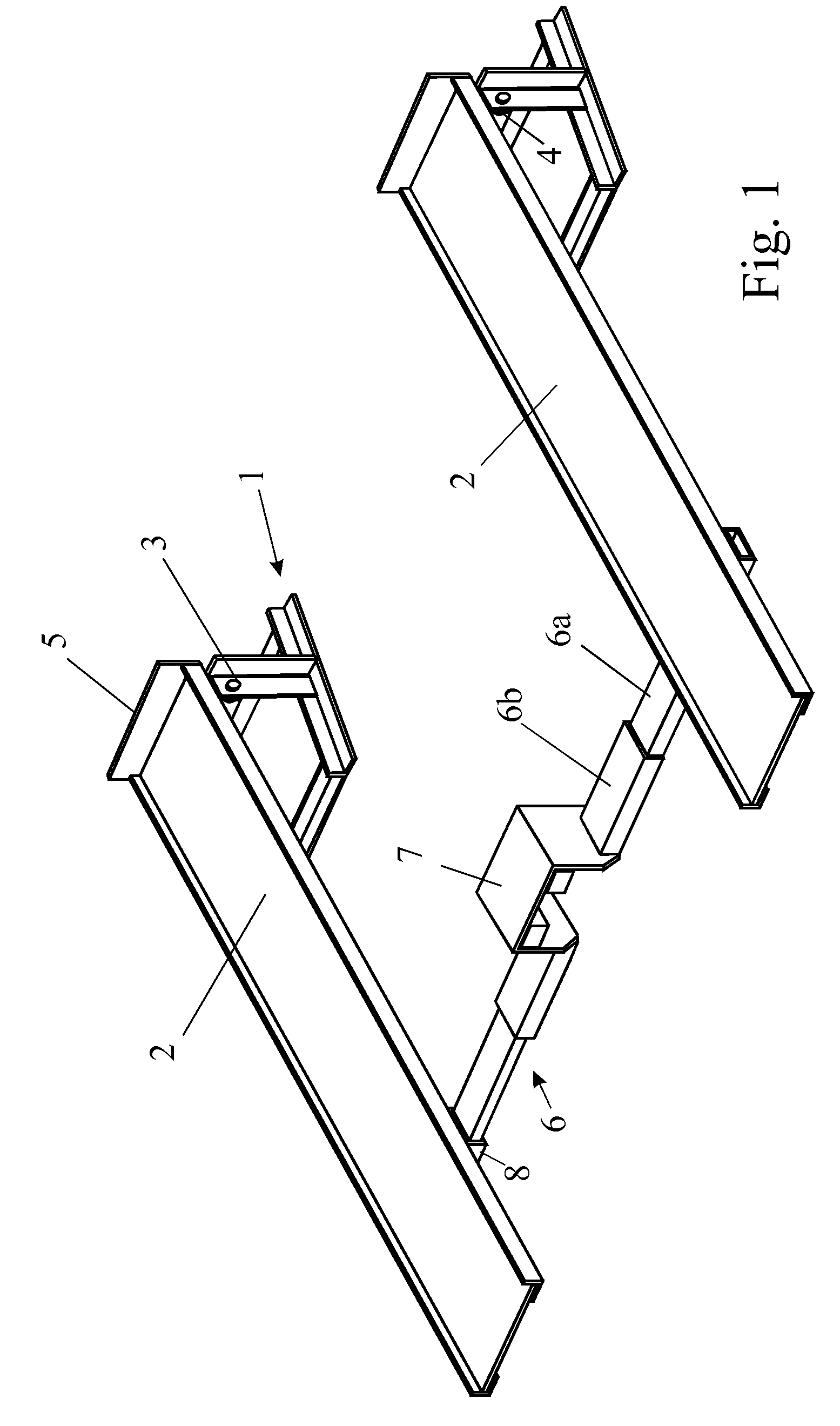
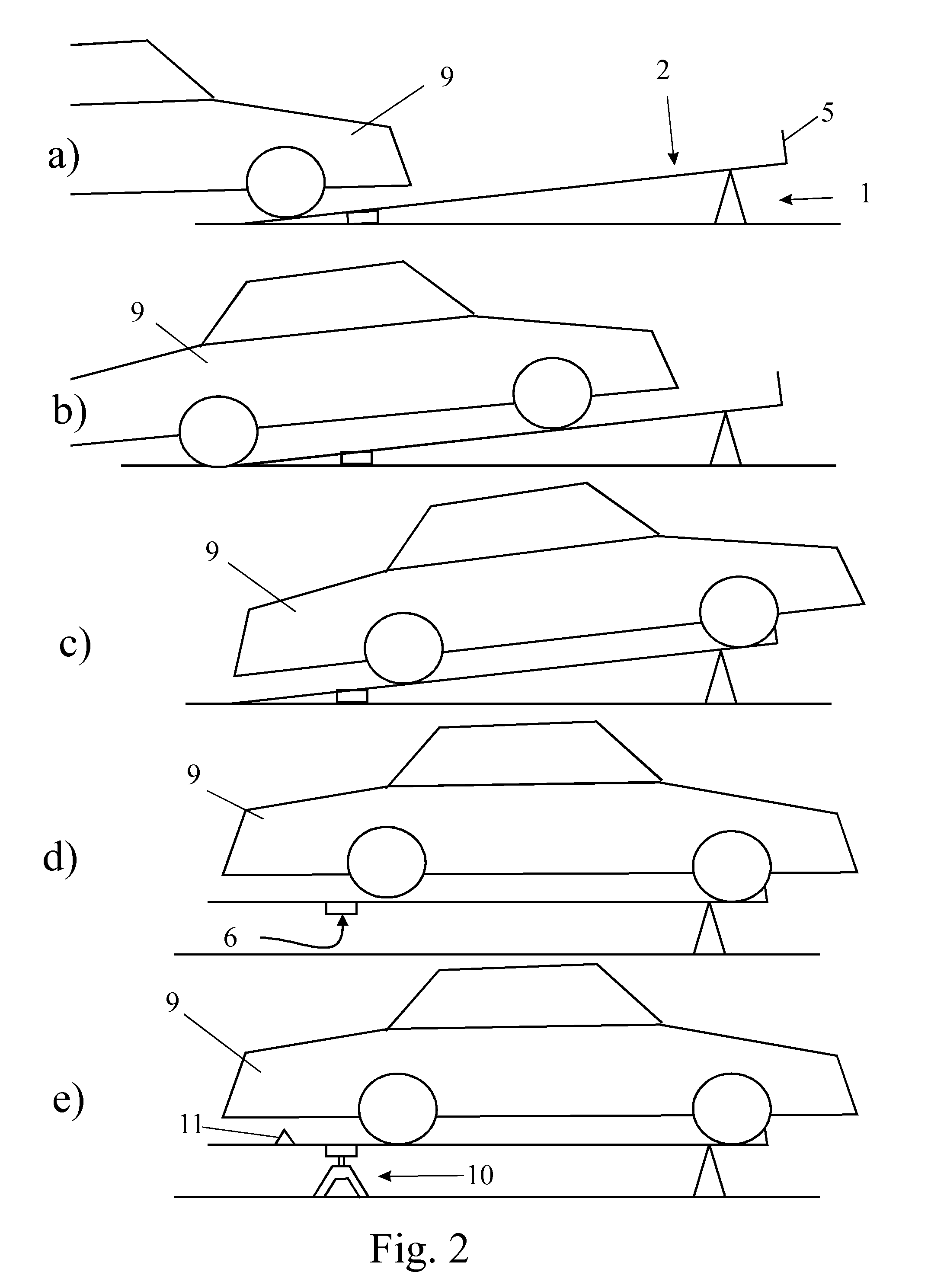
[0010]Embodiments of the present invention provide a vehicle lift suitable for a domestic garage or small workshop and enabling sufficient lift to provide working space underneath the vehicle without the risk and complexity of transferring the vehicle from a single jack to axle stands or blocks.
[0011]In some embodiments, a vehicle lift comprises a pair of parallel ramps each of which is pivoted to an upstanding support at one end and thereby movable between a substantially horizontal configuration and a slope downwards from the pivot, wherein the two ramps are connected by a cross-beam rigidly secured to the ramps and located towards the ends distal from the pivots but displaced therefrom such that the cross-beam bears against the ground when the ramps are in a downward position and wherein the cross-beam includes a jacking point engageable with a separable lifting jack and located substantially midway between the two ramps such that lifting forces are directed effectively through t...
PUM
 Abstract
Description
Claims
Application Information