Bone treatment systems and methods

a bone fracture and compression technology, applied in the field of vertebral compression fracture treatment systems, can solve the problems of fractures in the spine and hips, affecting mobility and quality of life, and the medical advances aimed at slowing or arresting bone loss from aging have not provided solutions to this problem, so as to accelerate polymerization, prevent further cement migration, and prolong the working time of bone cemen

Active Publication Date: 2014-04-15
DFINE INC
View PDF215 Cites 19 Cited by
  • Summary
  • Abstract
  • Description
  • Claims
  • Application Information

AI Technical Summary

Benefits of technology

[0019]Certain embodiments of the invention provide vertebroplasty systems and methods for sensing retrograde bone cement flows that can migrate along a fractured path toward a pedicle and risk leakage into the spinal canal. The physician can be alerted instantaneously of cement migration in a direction that may impinge on nerves or the spinal cord. Other embodiments include integrated sensing systems and energy delivery systems for applying energy to tissue and / or to bone cement that migrates in a retrograde direction wherein the energy polymerizes the cement and / or coagulates tissue to create a dam to prevent further cement migration. In another embodiment, the systems provide a cooling system for cooling bone cement in a remote container or injection cannula for controlling and extending the working time of bone cement. In another embodiment, the bone cement injection system includes a thermal energy emitter for warming bone cement within an injector or for applying sufficient energy to accelerate polymerization and thereby increase the viscosity of the bone cement.
[0020]In one embodiment, a computer controller is provided to controls cement inflow parameters from a hydraulic source, the sensing system and energy delivery parameters for selectively heating tissue or polymerizing cement at both the interior and exterior of the injector to thereby control all parameters of cement injection to reduce workload on the physician.
[0021]In another embodiment, a lubricous surface layer is provided in the flow passageway of the bone cement injector to inhibit sticking of the bone cement to the wall of the flow channel of the introducer, particularly when heating the cement.
[0023]In accordance with another embodiment, a bone treatment system is provided. The bone treatment system comprises an elongated injector having a flow passageway extending therethrough, a source of bone fill material coupleable to the flow passageway and configured to deliver a flow of bone fill material through the flow passageway, and a vapor source operatively coupleable to at least one channel in the injector that is in communication with the flow passageway for injecting vapor into the flow passageway to heat the bone fill material in the passageway.

Problems solved by technology

Medical advances aimed at slowing or arresting bone loss from aging have not provided solutions to this problem.
Osteoporosis affects the entire skeleton but most commonly causes fractures in the spine and hip.
Spinal or vertebral fractures also cause other serious side effects, with patients suffering from loss of height, deformity and persistent pain which can significantly impair mobility and quality of life.
Osteoporosis describes a condition of decreased bone mass that leads to fragile bones which are at an increased risk for fractures.
In an osteoporosis bone, the sponge-like cancellous bone has pores or voids that increase in dimension making the bone very fragile.
In an elderly patient, bone resorption can surpass bone formation thus resulting in deterioration of bone density.
Since the PMMA needs to be forced into the cancellous bone, the techniques require high pressures and fairly low viscosity cement.
Since the cortical bone of the targeted vertebra may have a recent fracture, there is the potential of PMMA leakage.
Leakage of PMMA during vertebroplasty can result in very serious complications including compression of adjacent structures that necessitate emergency decompressive surgery.
The exothermic reaction of PMMA carries potential catastrophic consequences if thermal damage were to extend to the dural sac, cord, and nerve roots.
Vertebroplasty patients often return with new pain caused by a new vertebral body fracture.
Leakage of cement into an adjacent disc space during vertebroplasty increases the risk of a new fracture of adjacent vertebral bodies.
Another life-threatening complication of vertebroplasty is pulmonary embolism.
The vapors from PMMA preparation and injection also are cause for concern.
In both higher pressure cement injection (vertebroplasty) and balloon-tamped cementing procedures (kyphoplasty), the methods do not provide for well controlled augmentation of vertebral body height.
Thus, the reduction of a vertebral compression fracture is not optimized or controlled in high pressure balloons as forces of balloon expansion occur in multiple directions.
Expansion of the balloon under high pressures close to cortical bone can fracture the cortical bone, typically the endplates, which can cause regional damage to the cortical bone with the risk of cortical bone necrosis.
Such cortical bone damage is highly undesirable as the endplate and adjacent structures provide nutrients for the disc.
Kyphoplasty also does not provide a distraction mechanism capable of 100% vertebral height restoration.
Further, the kyphoplasty balloons under very high pressure typically apply forces to vertebral endplates within a central region of the cortical bone that may be weak, rather than distributing forces over the endplate.

Method used


Image

  • Bone treatment systems and methods
  • Bone treatment systems and methods
  • Bone treatment systems and methods

Examples


Embodiment Construction

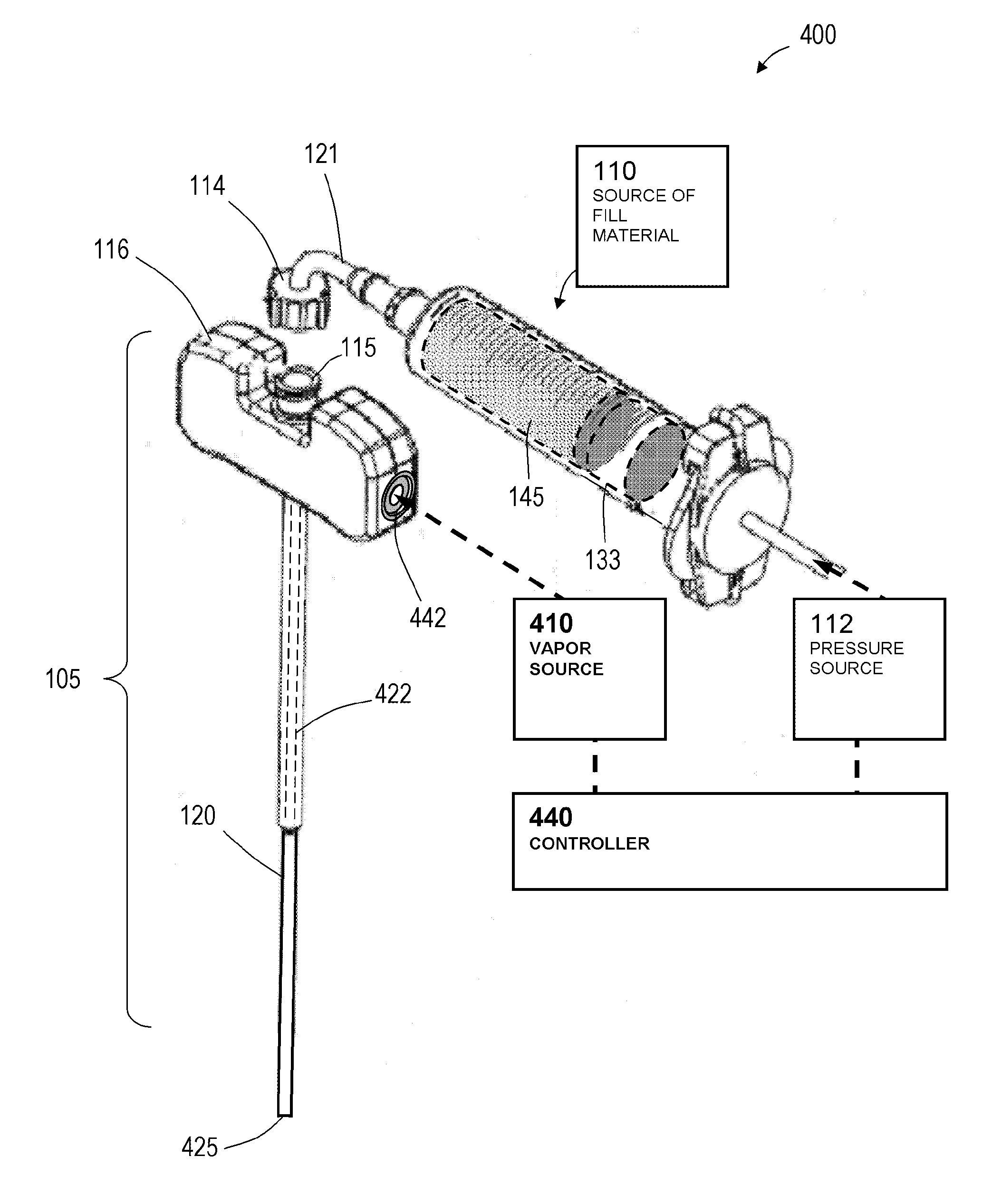
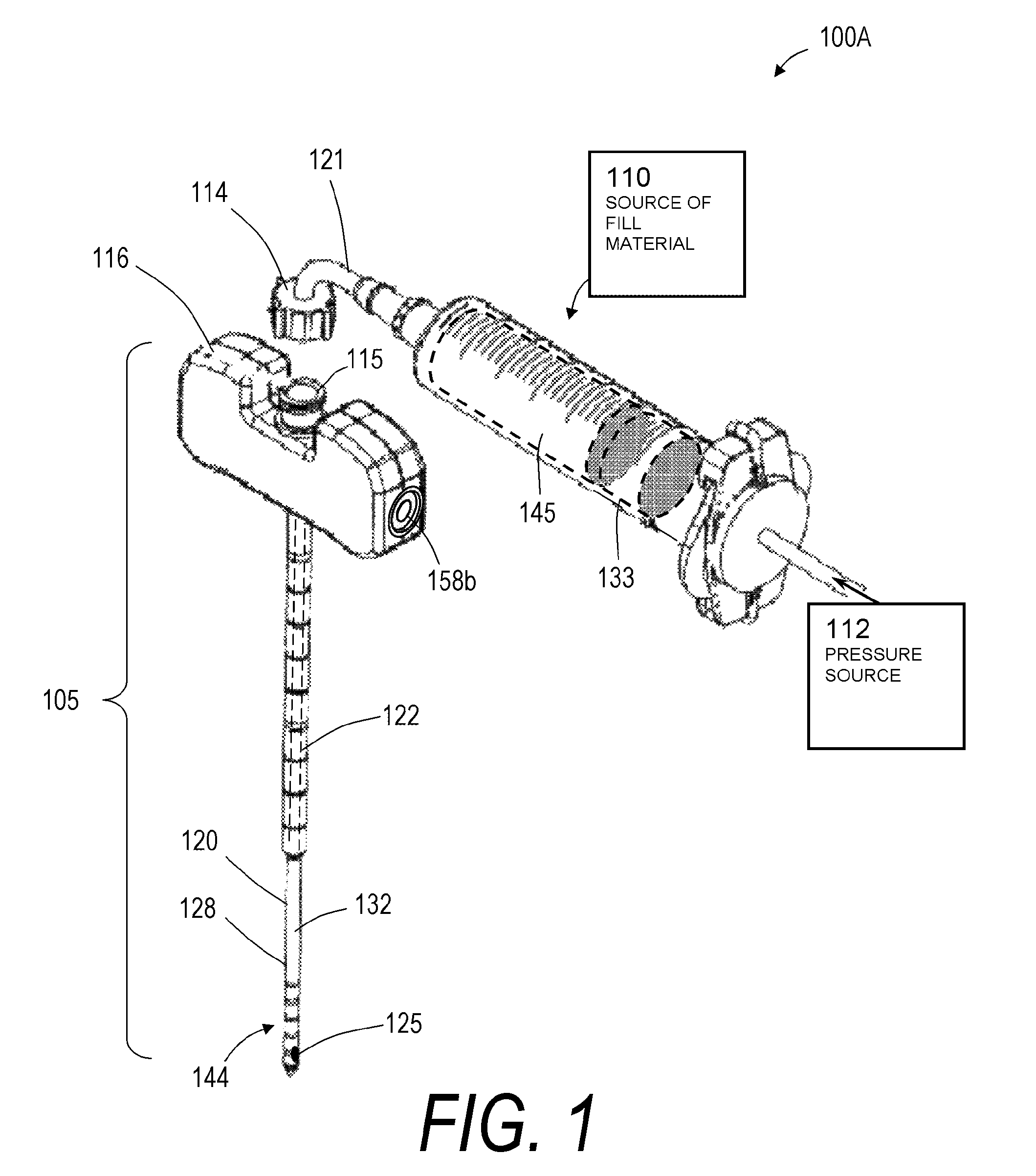
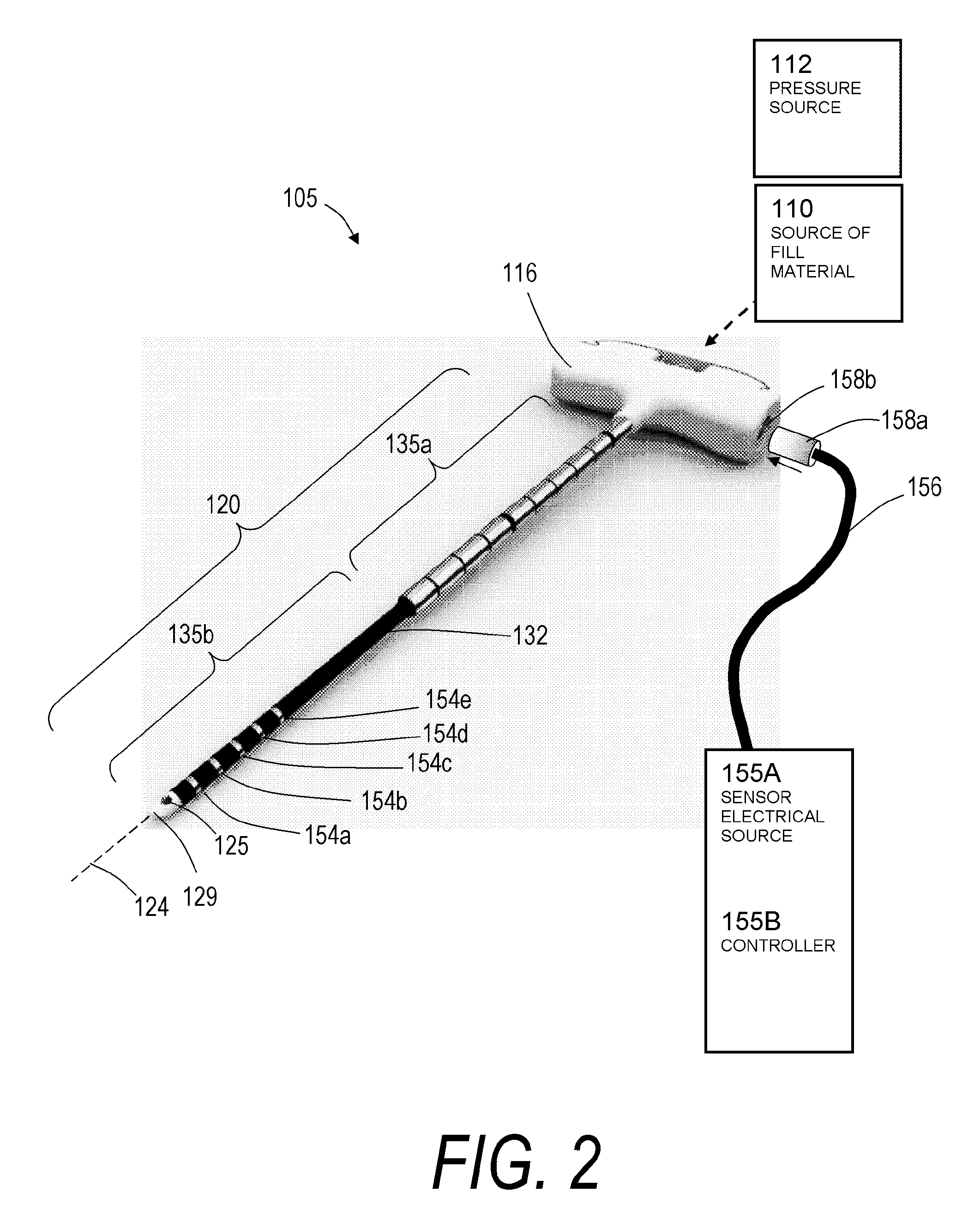
[0036]For the purpose of understanding the principles of the invention, reference will now be made to the embodiments illustrated in the drawings and accompanying text that describe different embodiments of the invention. Referring to FIGS. 1-2, one embodiment of a bone fill introducer or injector system 100A is shown that can be used for treatment of the spine in a vertebroplasty procedure. The system 100A includes a bone cement injector 105 that is coupled to source 110 of a bone fill material wherein the injection of the fill material is carried out by a pressure mechanism or source 112 operatively coupled to the source 110 of bone fill material. In one embodiment, as in FIG. 1, the pressure source 112 can be a hydraulic actuator that can be computer controlled, but the scope of the invention includes a manually operated syringe loaded with bone fill material, or any other pressurized source of fill material. The source 110 of fill material includes a coupling or fitting 114 for ...


PUM


Abstract

The present invention relates in certain embodiments to methods, systems, and devices for treating vertebral compression fractures. In one embodiment, a bone cement injector is advanced into bone and injects a bone cement flow through the injector and a vapor flow from at least one vapor outlet in the injector. In another embodiment, the bone treatment system comprises an elongated member having a flow passageway, a bone fill material source, and a vapor source coupleable to the flow passageway. Still another embodiment describes a vapor injection device having an elongated member with a flow passageway, the elongated member configured for insertion into a bone and for delivering a bone fill material through the flow passageway, and having at least one vapor channel in communication with the flow passageway to deliver a vapor into the flow passageway to heat a bone fill material flow.

Description

CROSS-REFERENCE TO RELATED APPLICATIONS[0001]This application claims the benefit of U.S. Provisional Patent Application No. 60 / 873,590, filed on Dec. 8, 2006, the entire contents of which are hereby incorporated by reference and should be considered a part of this specification. The present application is related to the following U.S. Patent Applications: App. Ser. No. 11 / 469,764 filed Sept. 1, 2006; App. Ser. No. 11 / 165,652 filed Jun. 24, 2005; App. Ser. No. 60 / 726,152 filed Oct. 13, 2005 titled Bone Treatment Systems and Methods; and App. Ser. No. 11 / 209,035 filed Aug. 22, 2005. The entire contents of all of the above applications are hereby incorporated by reference and should be considered a part of this specification.BACKGROUND OF THE INVENTION[0002]1. Field of the Invention[0003]The present invention relates in certain embodiments to systems for treating vertebral compression fractures. In some embodiments, systems and methods for treating bone are disclosed that include deliv...

Claims


Application Information

Patent Timeline
Patent Type & Authority Patents(United States)
IPC IPC(8): A61F2/00
CPCA61B2017/00544A61B17/8836A61B17/8822A61B17/7095A61B2017/00039
Inventor SHADDUCK, JOHN H.TRUCKAI, CSABA
Owner DFINE INC
Why Eureka
Try Eureka