
Implantable pressure-actuated drug delivery systems and methods of manufacture and use

a technology of pressure-actuated drug delivery and implantable pressure, which is applied in the direction of blood vessels, prostheses, manufacturing tools, etc., can solve the problems of emergency angioplasty, sudden clot of stents, and difficult coordination

Active Publication Date: 2014-04-15
THE JOHN HOPKINS UNIV SCHOOL OF MEDICINE
View PDF25 Cites 0 Cited by
  • Summary
  • Abstract
  • Description
  • Claims
  • Application Information

AI Technical Summary

Benefits of technology

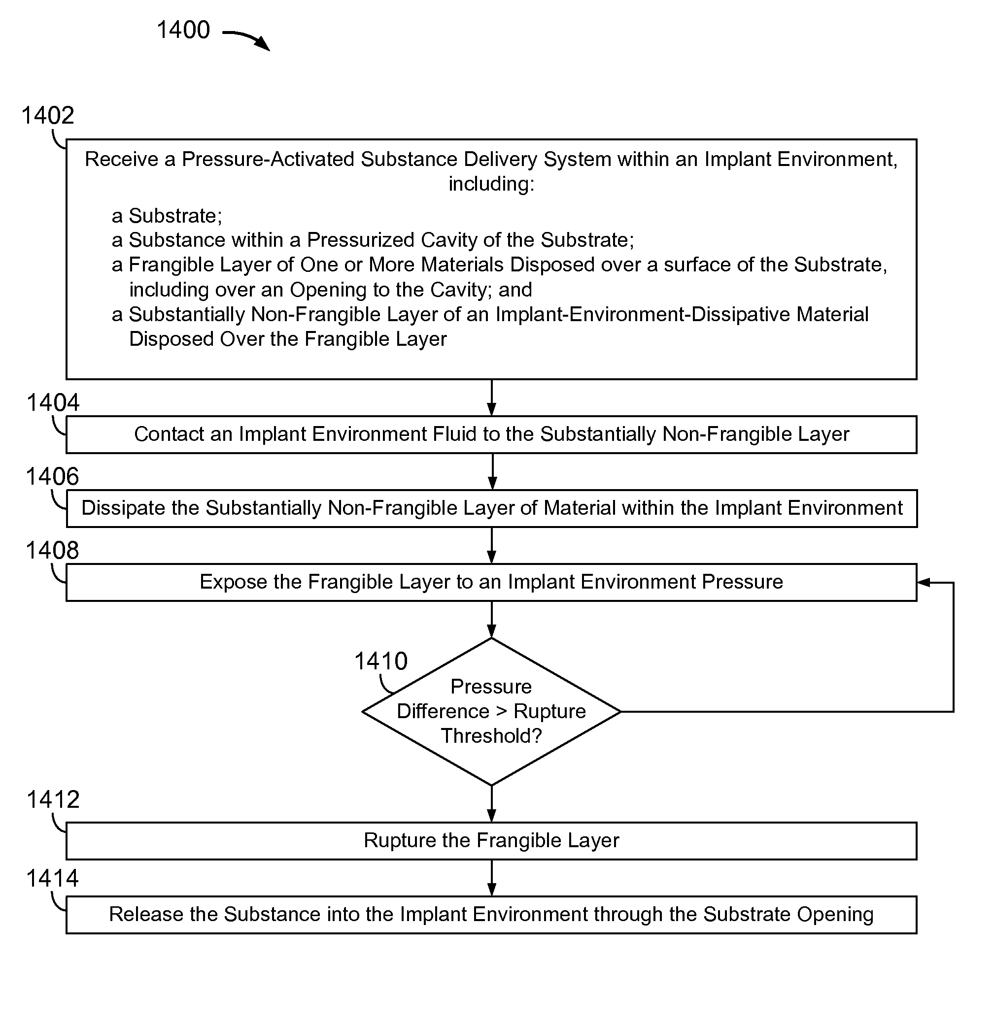
The invention is about a device that can pressure or vacuum a cavity and protect a diaphragm from rupturing prematurely. It can also dissipate in an implant environment. The device can release or deliver substances into the implant environment when there is a pressure difference across the diaphragm.

Problems solved by technology

Stents, however, have been known to abruptly clot.
Conventional stent clot treatment includes emergency angioplasty, which is expensive, difficult to coordinate, and accompanied by relatively high mortality rates.
However, drug-eluting stents have been shown to increase the likelihood of abrupt in-stent clot formation.
Stents have been textured and coated with antibodies and proteins to attract native cell coverings in attempts to promote vessel healing and reduce clot formation, without much success and, in some cases, with increased clotting.
Furthermore, such passive systems are not able to sense nor adapt to new clots that may occur.
Drugs are released with pre-determined kinetics, and these systems cannot sense nor respond to new, abrupt environmental changes such as clotting.
Active drug delivery systems deliver drugs in response to an external stimulus, but conventional systems require a bulky or externalized power source, a separate sensor and are unsuitable for intracoronary application.

Method used


Image

  • Implantable pressure-actuated drug delivery systems and methods of manufacture and use
  • Implantable pressure-actuated drug delivery systems and methods of manufacture and use
  • Implantable pressure-actuated drug delivery systems and methods of manufacture and use

Examples


Embodiment Construction

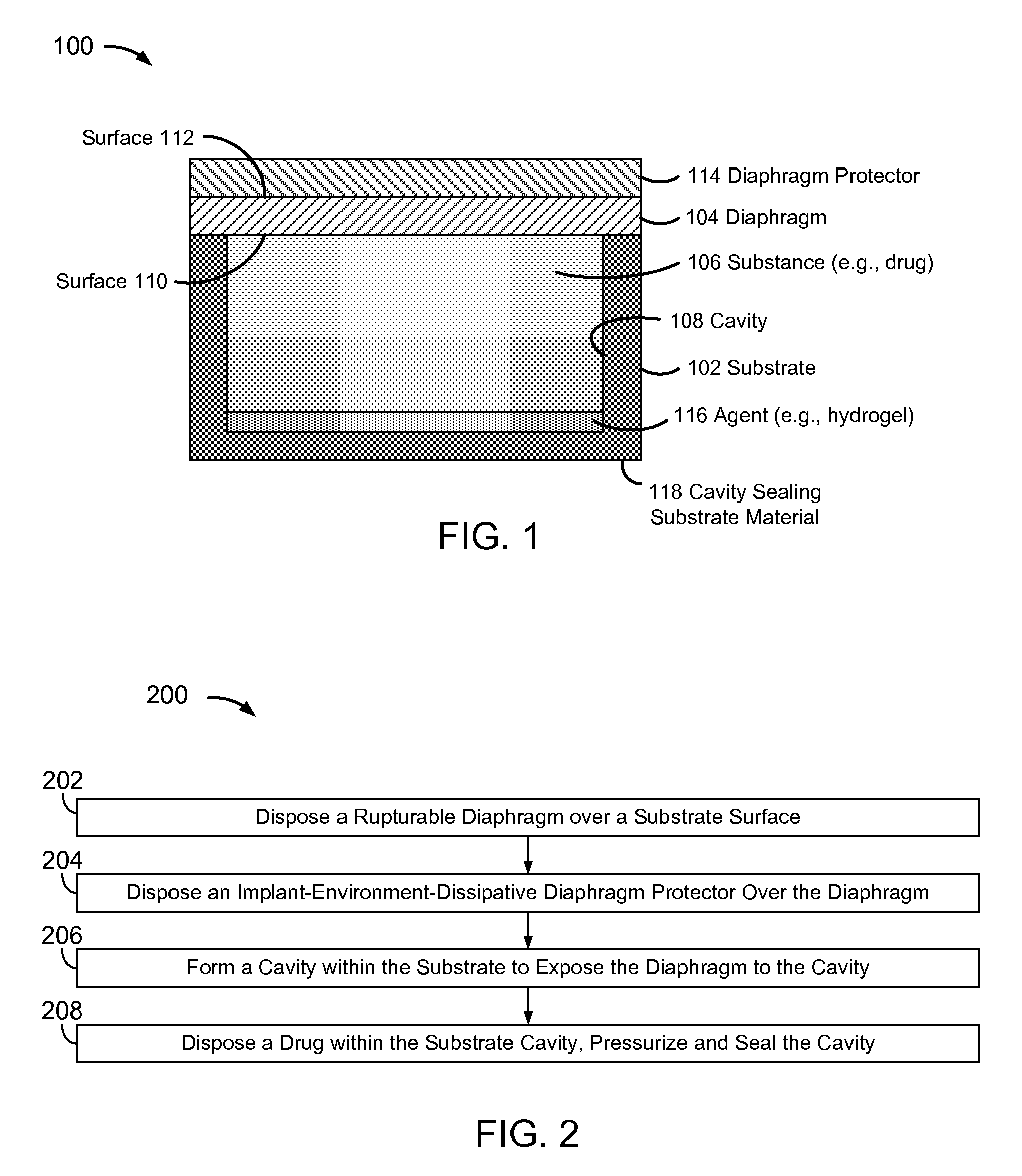
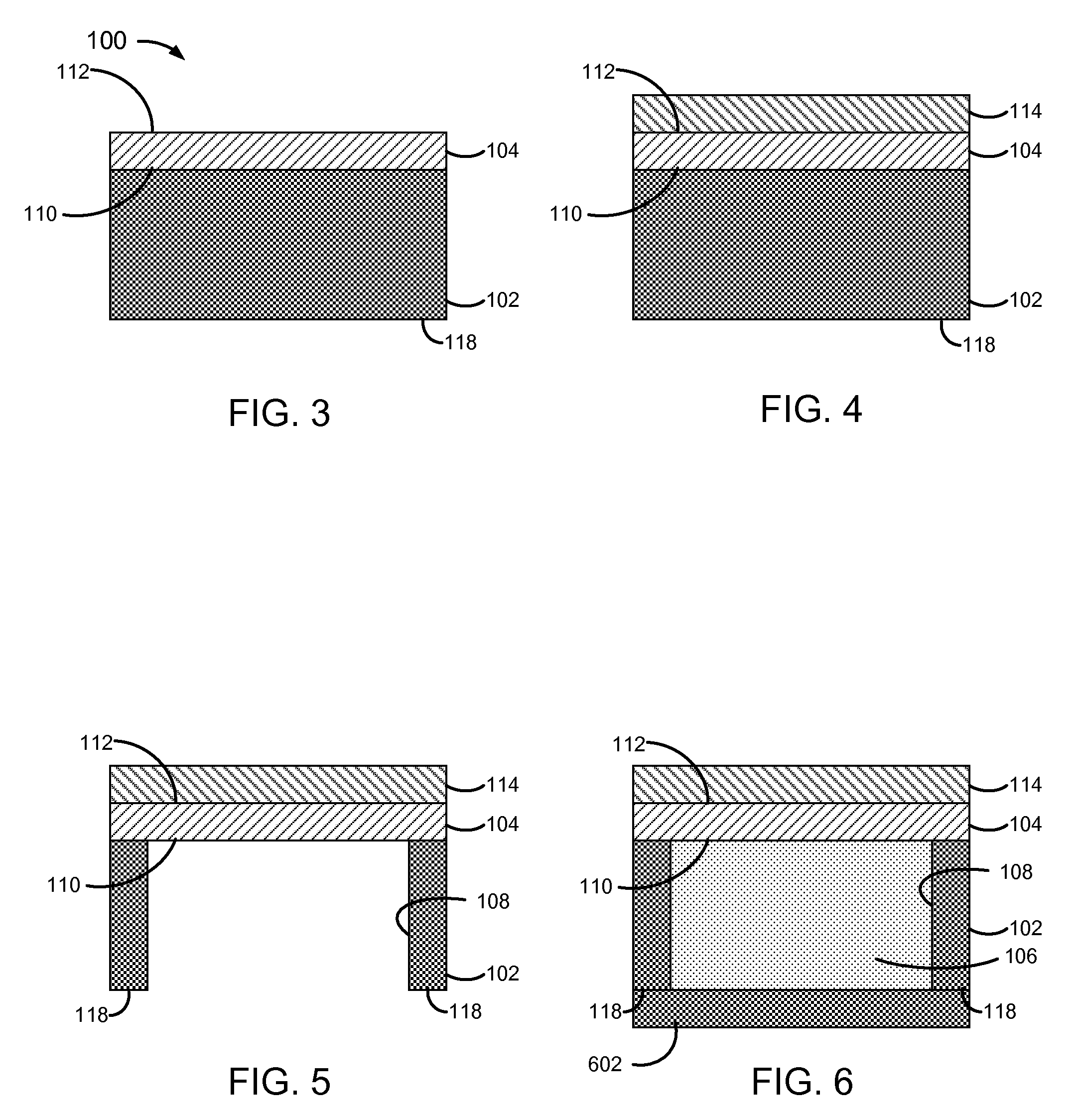
[0032]FIG. 1 is a block diagram of a pressure-actuated drug delivery system 100, including a substrate 102 and a pressure-rupturable diaphragm 104 to releasably retain a drug 106 within a cavity 106 of substrate 102.

[0033]Diaphragm 104 may be configured to rupture upon a pre-determined pressure difference across first and second surfaces or sides 110 and 112, referred to herein as a rupture threshold. A pressure on surface 110 may be a pre-determined pressure, which may be set during fabrication and / or prior to or at the time of implantation. A pressure on surface 112 may correspond to an implant environment pressure, such as a vascular blood pressure.

[0034]The rupture threshold may be a function of a material and physical characteristics of diaphragm 104. Physical characteristics may include thickness, and / or other physical features of diaphragm 104. For example, surface 112 may have ridges, walls, posts, grooves, depressions, and / or other physical features formed therein, which ma...


PUM

PropertyMeasurementUnit
rupture timeaaaaaaaaaa
rupture pressureaaaaaaaaaa

Abstract

Implantable pressure-actuated systems to deliver a drug and / or other substance in response to a pressure difference between a system cavity and an exterior environment, and methods of fabrication and use. A pressure-rupturable membrane diaphragm may be tuned to rupture at a desired rupture threshold, rupture site, with a desired rupture pattern, and / or within a desired rupture time. Tuning may include material selection, thickness control, surface patterning, substrate support patterning. The cavity may be pressurized above or evacuated below the rupture threshold, and a diaphragm-protective layer may be provided to prevent premature rupture in an ambient environment and to dissipate within an implant environment. A drug delivery system may be implemented within a stent to release a substance upon a decrease in blood pressure. The cavity may include a thrombolytic drug to or other substance to treat a blood clot.

Description

CROSS REFERENCE TO RELATED APPLICATIONS[0001]This application claims the benefit of U.S. Provisional Patent Application No. 61 / 292,339, filed Jan. 5, 2010, which is incorporated herein by reference in its entirety.BACKGROUND[0002]1. Technical Field[0003]Mechanically actuated substance delivery methods and systems, including implantable, pressure-actuated drug delivery methods and systems.[0004]2. Related Art[0005]Coronary stents are commonly used to treat heart attacks. Stents, however, have been known to abruptly clot. Conventional stent clot treatment includes emergency angioplasty, which is expensive, difficult to coordinate, and accompanied by relatively high mortality rates.[0006]Stents have been coated with drugs (“drug-eluting stents”) to reduce the formation of scar tissue. However, drug-eluting stents have been shown to increase the likelihood of abrupt in-stent clot formation.[0007]Stents have been textured and coated with antibodies and proteins to attract native cell cov...

Claims


Application Information

Patent Timeline
Patent Type & Authority Patents(United States)
IPC IPC(8): A61F2/82
CPCA61F2/82C23C14/22A61K9/0012A61K9/0024A61K9/0097A61L31/16A61M31/002A61L31/145B05D1/005A61L33/0017A61F2250/0068A61F2250/0071A61L2300/42A61L2300/602Y10T29/49826A61L2420/02A61L2300/606A61F2240/001
Inventor HWANG, CHAO-WEITOMEY, HALA J.ROSAR, JON R.MATTESON, III, ROBERT C.COLES, JR., GEORGE L.BENKOSKI, JASON J.TREXLER, MORGANA M.
Owner THE JOHN HOPKINS UNIV SCHOOL OF MEDICINE
Learn More