Control for switching between PWM and PFM operation in a buck converter

a buck converter and control technology, applied in the direction of electric variable regulation, process and machine control, instruments, etc., can solve the problems of reducing the switching frequency and improving efficiency, and the pwm converter optimized for mid and high load current may not be very efficient at lowering load current, so as to reduce the loss of ac inductance, the effect of reducing the rms inductor curren

Active Publication Date: 2014-04-15
TEXAS INSTR INC
View PDF8 Cites 15 Cited by
  • Summary
  • Abstract
  • Description
  • Claims
  • Application Information

AI Technical Summary

Benefits of technology

[0022]It has been found that the above-described approach sometimes results in improper switching between operating modes. By way of example, sometimes the mode control circuitry will detect what is perceived to be low load current conditions and switch from the PWM mode to the PFM mode. While in the PFM mode, this same perceived load current will indicate that the current is sufficiently high to warrant immediately switching back to the PWM. This improper shifting between operating modes under certain operating conditions is obviously undesirable. There is a need for mode control circuitry which is capable of measuring load currents with sufficient accuracy in both the PWM and PFM operation so that this inappropriate shifting between operating modes is either eliminated or substantially reduced. As will become apparent from a reading of the following Detailed Description of the invention together with the drawings, the present invention addresses these and other shortcomings of the prior art.

Problems solved by technology

However, at light loads, AC loses predominate so that decreasing the switching frequency improves efficiency.
It can be seen from the above, that a PWM converter optimized for mid and high load current may not be very efficient at lower load currents.
Further, the size of the runs ripple current for PWM can vary considerably since it is related to the difference between Vin and Vout, with PFM operation resulting in lower rms inductor currents and thus lower ac inductor losses.
It has been found that the above-described approach sometimes results in improper switching between operating modes.
This improper shifting between operating modes under certain operating conditions is obviously undesirable.

Method used


Image

  • Control for switching between PWM and PFM operation in a buck converter
  • Control for switching between PWM and PFM operation in a buck converter
  • Control for switching between PWM and PFM operation in a buck converter

Examples


Embodiment Construction

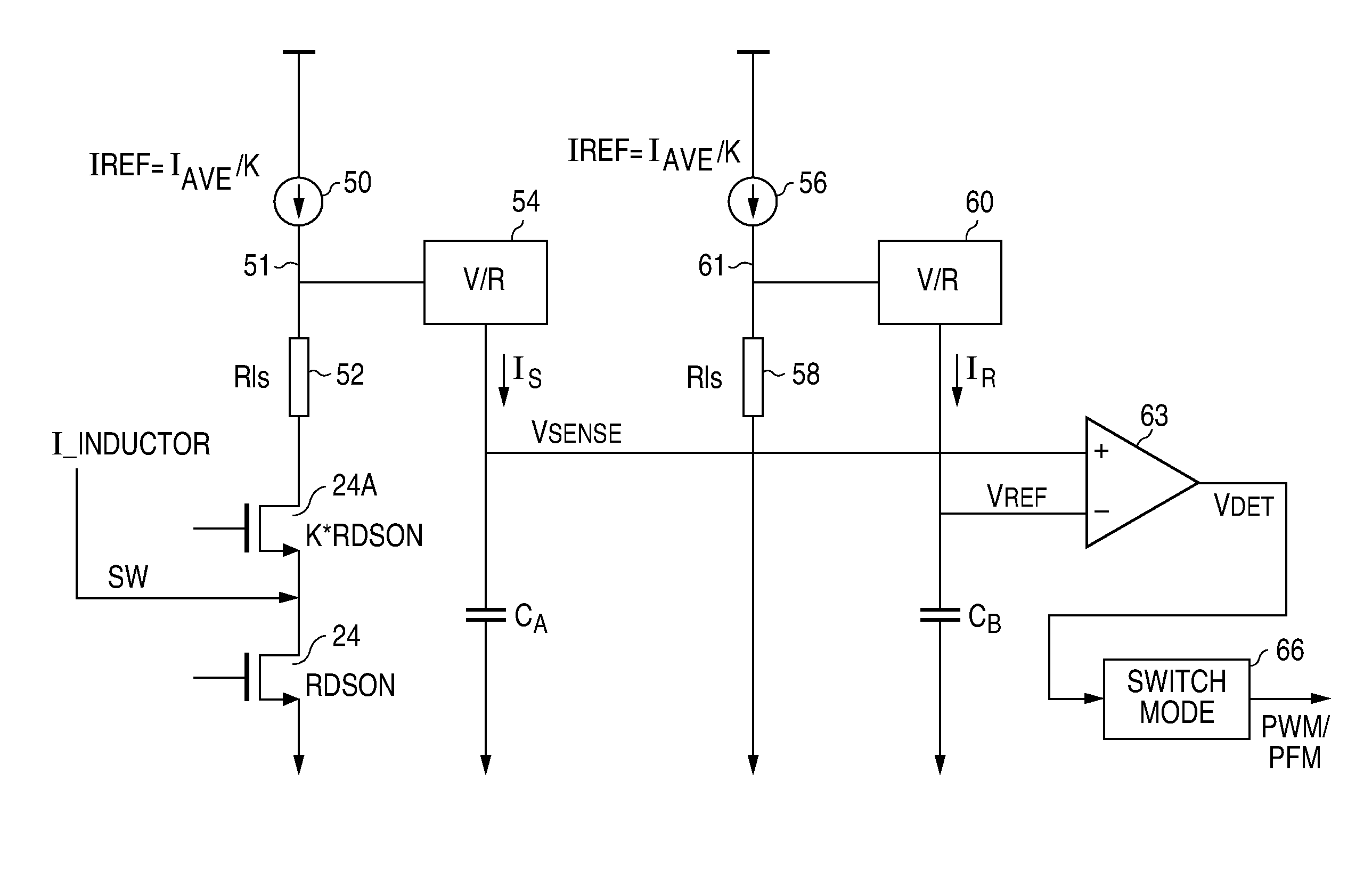
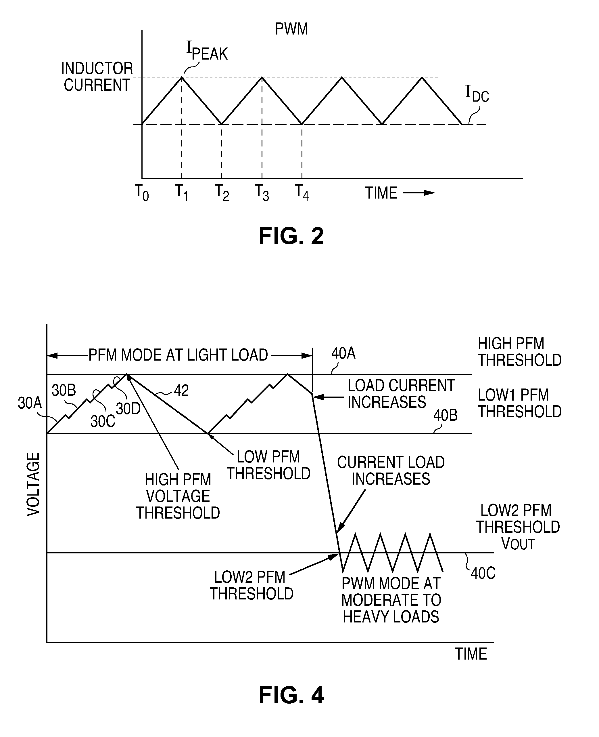
[0033]Referring again to the drawings, FIGS. 5A and 5B further illustrate the operation of prior art mode control circuitry based upon perceived measurements of the average load current. As previously noted, the specified load current level for switching from PFM to PWM operation is determined by selection of the peak inductor current 26 depicted in FIG. 3B. However, in either mode, a peak current detector current measurement of Ipeak / 2 does not reflect the actual average load current.

[0034]FIG. 5A shows an exemplary inductor current waveform 46 during PWM operation. Current level Ipeak, as previously noted, is specified in connection with PFM operation, and is used by the mode control circuitry for switching between the two operating modes. Ideally, when the average inductor current in the PFM mode has increased to Ipeak / 2, the mode will change to PWM and, conversely, when the average inductor current has dropped to Ipeak / 2 in PWM, the mode will change to PFM. Inspection of wavefor...


PUM


Abstract

A buck switching voltage regulator, with high side and low side switching transistors, includes mode control circuitry for switching between PWM and PFM modes based on sensing inductor current through the low side switch during switching cycle OFF times (inductor discharge). Mode switching is based on comparing a an integrated inductor current sense signal with an integrated reference signal corresponding to a predefined average inductor current IAVE. In one embodiment, a mode switching condition is based in part on [IVALLEY=21AVE−IPEAK], where IPEAK is a detected peak inductor current at the beginning of an OFF time, and IVALLEY is an inductor current value determined by IAVE and IPEAK.

Description

BACKGROUND OF THE INVENTION[0001]1. Field of the Invention[0002]The present invention relates generally to switching voltage regulators and in particular to a control apparatus for accurately controlling switching between a PWM mode and a PFM mode of operation in a multimode buck DC-DC converter.[0003]2. Description of Related Art[0004]Switching voltage regulators are commonly used to provide a regulated voltage source derived from a power source such as a battery. One common type of switching regulator operates as a step down regulator (buck converter) that provides a voltage output which is smaller than the input voltage utilizing pulse width modulation (PWM). FIG. 1 is a simplified diagram of a conventional buck converter, with the control circuitry not being depicted. An inductor L is provided having one terminal connected to the regulated output voltage Vout node. The other terminal of the inductor is connected to the input voltage node Vin by way of a P type transistor switch ...

Claims


Application Information

Patent Timeline
Patent Type & Authority Patents(United States)
IPC IPC(8): H02M3/156H02M1/00
CPCH02M2001/0009Y02B70/16H02M3/156H02M2001/0032H02M3/158Y02B70/10H02M1/0009H02M1/0032
Inventor JU, SHU-ING
Owner TEXAS INSTR INC
Why Eureka
Try Eureka