Projection zoom lens and projection display apparatus

a technology of projection zoom and projection display, which is applied in the field of projection zoom, can solve the problems of long back focus, and achieve the effects of large corrective operation effect, reduced manufacturing costs, and large back focus

Inactive Publication Date: 2014-04-15
FUJIFILM CORP
View PDF17 Cites 6 Cited by
  • Summary
  • Abstract
  • Description
  • Claims
  • Application Information

AI Technical Summary

Benefits of technology

[0007]The projection zoom lens described in Patent Document 1 has neither a high zoom ratio nor a large angle of view that satisfy the recent market needs. The projection zoom lens described in Patent Document 2 has a relatively high zoom ratio of not less than 1.5 but the current market demands a lens having a broader angle of view than that of the projection zoom lens described in Patent Document 2. The projection zoom lens described in Patent Document 3 has a high zoom ratio of not less than 1.5 with a large total angle of view of not less than 60°, but it cannot be said that it ensures a sufficient back focus.
[0029]According to the first projection zoom lens of the present invention and the first projection display apparatus of the present invention, a first lens group having a negative power, a second lens group having a positive power, a third lens group having a positive power, a fourth lens group having a negative power, a fifth lens group having a positive power, and a sixth lens group having a positive power are arranged in this order from the magnification side and the reduction side is made telecentric, in which the projection zoom lens is configured such that the first and sixth lens groups are fixed while the second to fifth lens groups are moved along the axis of the projection zoom lens at the time of zooming, the fourth lens group is composed of one negative lens whose magnification side surface has a greater curvature in absolute value than that of the reduction side surface of the lens, and the zoom lens is configured to satisfy the conditional expression (1): −12.0<f4 / fw<−5.0. This allows the projection zoom lens and projection display apparatus to have a wide angle of field, a high zoom ratio, and a long back focus while various types of aberrations are corrected satisfactorily. For example, a back focus that allows easy insertion of a luminous flux combining optical system may be ensured.
[0030]Generally, the amount of movement of each lens group is inevitably increased in a zoom lens having a high zoom ratio. If the amount of movement of each lens group is increased as described above, deterioration in the balance of aberrations, such as spherical aberration and field curvature, occurs at the wide angle end and telephoto end. Consequently, by giving a negative power to an intermediate lens group of the moving lens groups (e.g., the fourth lens group), that is, by disposing a lens group that operates correctively to a large extent between lens groups having a large amount of movement and a large amount of zooming, the deterioration in the balance of aberrations, such as spherical aberration and field curvature, at the wide angle end and telephoto end may be reduced.
[0031]Further, as the projection zoom lens is configured to satisfy the conditional expression (1), the corrective operation effect may be obtained reliably and the deterioration in the balance of aberrations, such as spherical aberration and field curvature, at the wide angle end and telephoto end may be reduced reliably while ensuring a high zoom ratio.
[0034]The composition of the fourth lens group with only one negative lens whose magnification side surface has a greater curvature in absolute value than that of the reduction side surface allows reduced manufacturing costs.
[0035]According to the second projection zoom lens of the present invention and the second projection display apparatus of the present invention, the fourth lens group is composed of one meniscus shaped negative with a convex surface on the reduction side and the zoom lens is configured to satisfy the conditional expression (6): 30<νd. This allows a variation in chromatic aberration at the time of zooming to be minimized.

Problems solved by technology

Further, for an optical system that uses a plurality of light valves, a space for inserting a luminous flux combining optical system, such as a combining prism or the like, for combining each color luminous flux from each light valve is required, thereby resulting in a long back focus.

Method used


Image

  • Projection zoom lens and projection display apparatus
  • Projection zoom lens and projection display apparatus
  • Projection zoom lens and projection display apparatus

Examples


example 1

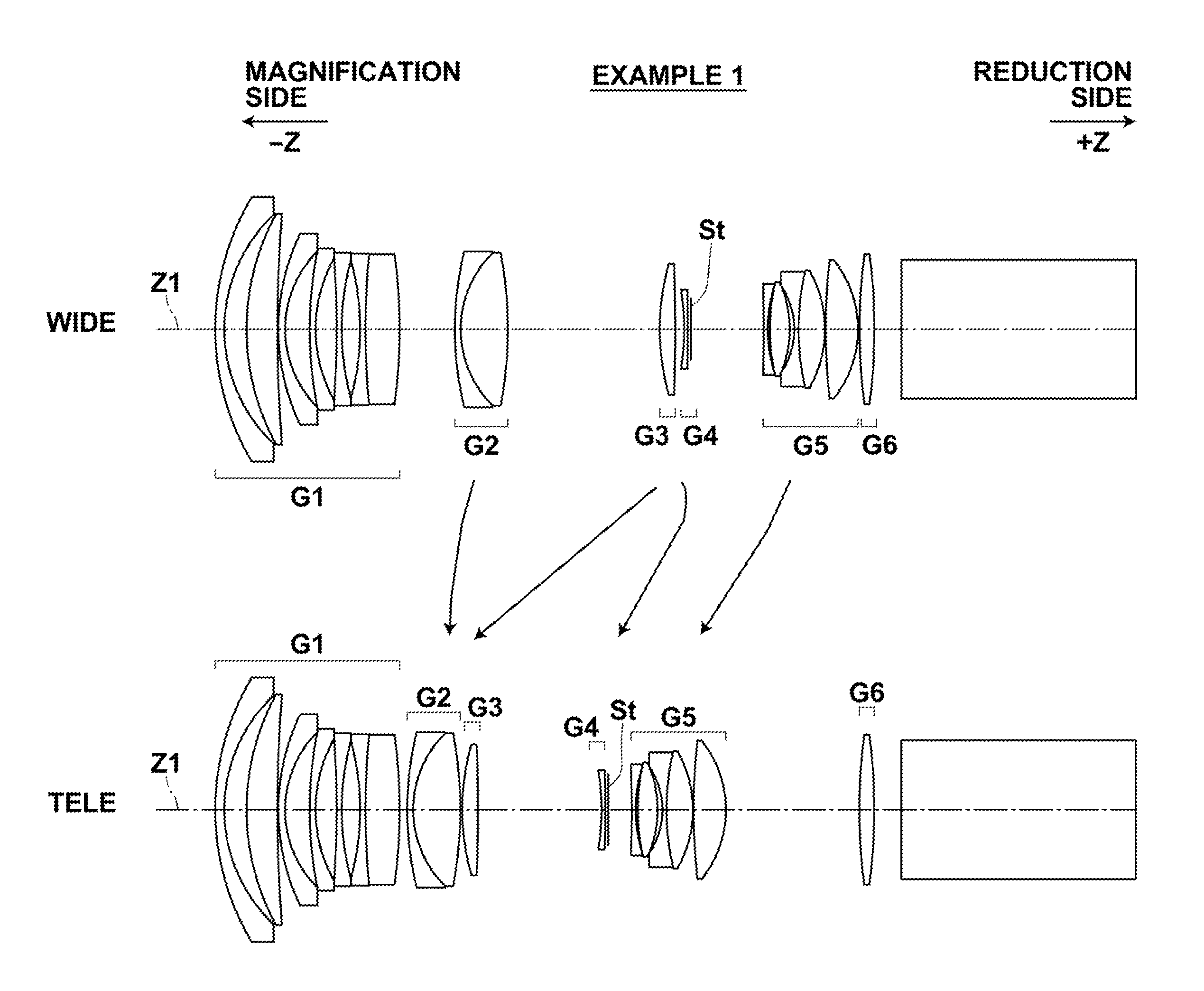
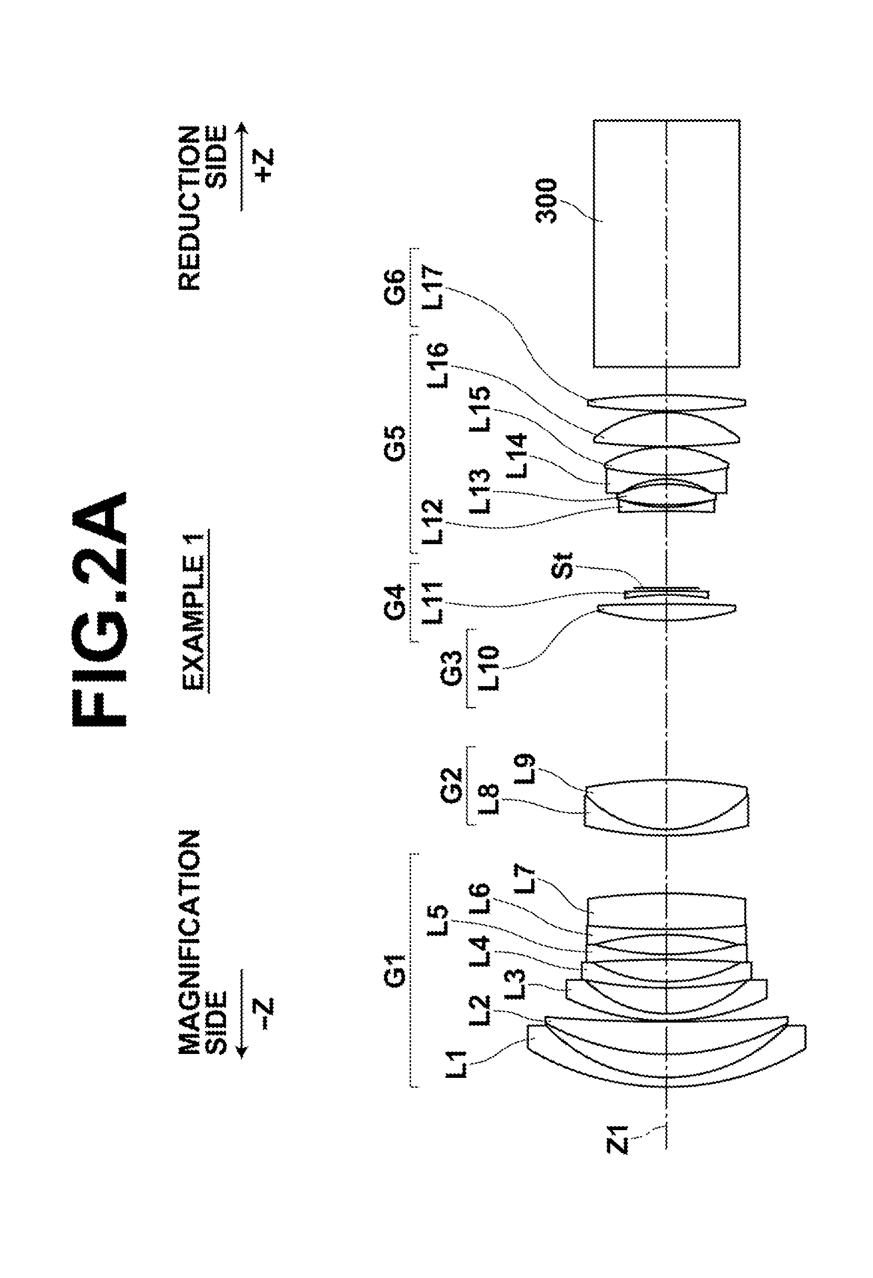
[0088]FIGS. 2A, 2B illustrate a projection zoom lens of Example 1. FIG. 2A illustrates the projection zoom lens in detail and FIG. 2B comparatively illustrates the positions of each lens group of the projection zoom lens of Example 1 at the wide angle end (indicated by “WIDE” in the drawing) and telephoto end (indicated by “TELE” in the drawing).

[0089]The projection zoom lens of Example 1 includes six lens groups and corresponds to both of the first invention and second invention. The first lens group G1 is composed of seven lenses of a first group first lens L1 to a first group seventh lens L7, the second lens group G2 is composed of two lenses of a second group first lens L8 and a second group second lens L9, and the third lens group G3 is composed of one lens of a third group first lens L10.

[0090]The fourth lens group G4 is composed of one lens of a fourth group first lens L11, the fifth lens group is composed of five lenses of a fifth group first lens L12 to fifth group fifth le...

example 2

[0108]FIGS. 3A, 3B illustrate a projection zoom lens of Example 2. FIG. 3A illustrates the projection zoom lens in detail and FIG. 3B comparatively illustrates the positions of each lens group of the projection zoom lens of Example 2 at the wide angle end (indicated by “WIDE” in the drawing) and telephoto end (indicated by “TELE” in the drawing). The projection zoom lens of Example 2 also includes six lens groups. The projection zoom lens of Example 1 includes six lens groups and corresponds to both of the first invention and second invention.

[0109]The first lens group G1 is composed of five lenses of a first group first lens L1 to a first group fifth lens L5, the second lens group G2 is composed of four lenses of a second group first lens L6 to a second group fourth lens L9, the third lens group G3 is composed of one lens of a third group first lens L10.

[0110]The fourth lens group G4 is composed of one lens of a fourth group first lens L11, the fifth lens group G5 is composed of fi...

example 3

[0118]FIGS. 4A, 4B illustrate a projection zoom lens of Example 3. FIG. 4A illustrates the projection zoom lens in detail and FIG. 4B comparatively illustrates the positions of each lens group of the projection zoom lens of Example 3 at the wide angle end (indicated by “WIDE” in the drawing) and telephoto end (indicated by “TELE” in the drawing). The projection zoom lens of Example 3 also includes six lens groups and corresponds to the first invention but does not correspond to the second invention.

[0119]The first lens group G1 is composed of six lenses of a first group first lens L1 to a first group sixth lens L6, the second lens group G2 is composed of two lenses of a second group first lens L7 and a second group second lens L8, the third lens group G3 is composed of one lens of a third group first lens L9.

[0120]The fourth lens group G4 is composed of one lens of a fourth group first lens L10, the fifth lens group G5 is composed of five lenses of a fifth group first lens L11 to a ...


PUM


Abstract

A projection zoom lens having broad angle of view, high zoom ratio, and large back focus while aberrations are corrected satisfactorily, including a negative first lens group, a positive second lens group, a positive third lens group, a negative fourth lens group, a positive fifth lens group, and a positive sixth lens group from the magnification side and is telecentric on the reduction side. When zooming, the first and sixth lens groups are fixed while the second to fifth lens groups are moved and the fourth lens group is composed of one negative lens whose magnification side surface has a greater curvature in absolute value than that of the reduction side surface, and the zoom lens satisfies conditional expression (1): −12.0<f4 / fw<−5.0, where f4 is focal length of the fourth lens group, and fw is focal length of the entire lens system at the wide angle end.

Description

BACKGROUND OF THE INVENTION[0001]1. Field of the Invention[0002]The present invention relates to a projection zoom lens that includes six lens groups and a projection display apparatus using the same.[0003]2. Description of the Related Art[0004]Recently, projection display devices using a transmissive or reflective liquid crystal or projection display devices using a light valve, such as DMD display devices, have been used widely. As projection lenses for use with such projection display devices, projection lenses that use zoom lenses capable of changing the size of a projection image have been used increasing as described, for example, in Japanese Unexamined Patent Publication No. 2004-138640 (Patent Document 1), Japanese Unexamined Patent Publication No. 2006-234893 (Patent Document 2), and Japanese Unexamined Patent Publication No. 2009-020189 (Patent Document 3). Recently, zoom lenses having a high rate of change in the size of a projection image, i.e., having a high zoom ratio ...

Claims


Application Information

Patent Timeline
Patent Type & Authority Patents(United States)
IPC IPC(8): G02B9/62
CPCG02B13/16G02B15/14G02B15/177G03B21/14G02B15/20G02B15/1465
Inventor AMANO, MASARU
Owner FUJIFILM CORP
Why Eureka
Try Eureka