
Behavior based signatures

a behavior-based signature and signature technology, applied in the field of computer security, can solve the problems of large number of ineffective malware signatures in use, and easy circumvention of signature-based detection by changing conten

Active Publication Date: 2014-04-15
CA TECH INC
View PDF4 Cites 82 Cited by
  • Summary
  • Abstract
  • Description
  • Claims
  • Application Information

AI Technical Summary

Benefits of technology

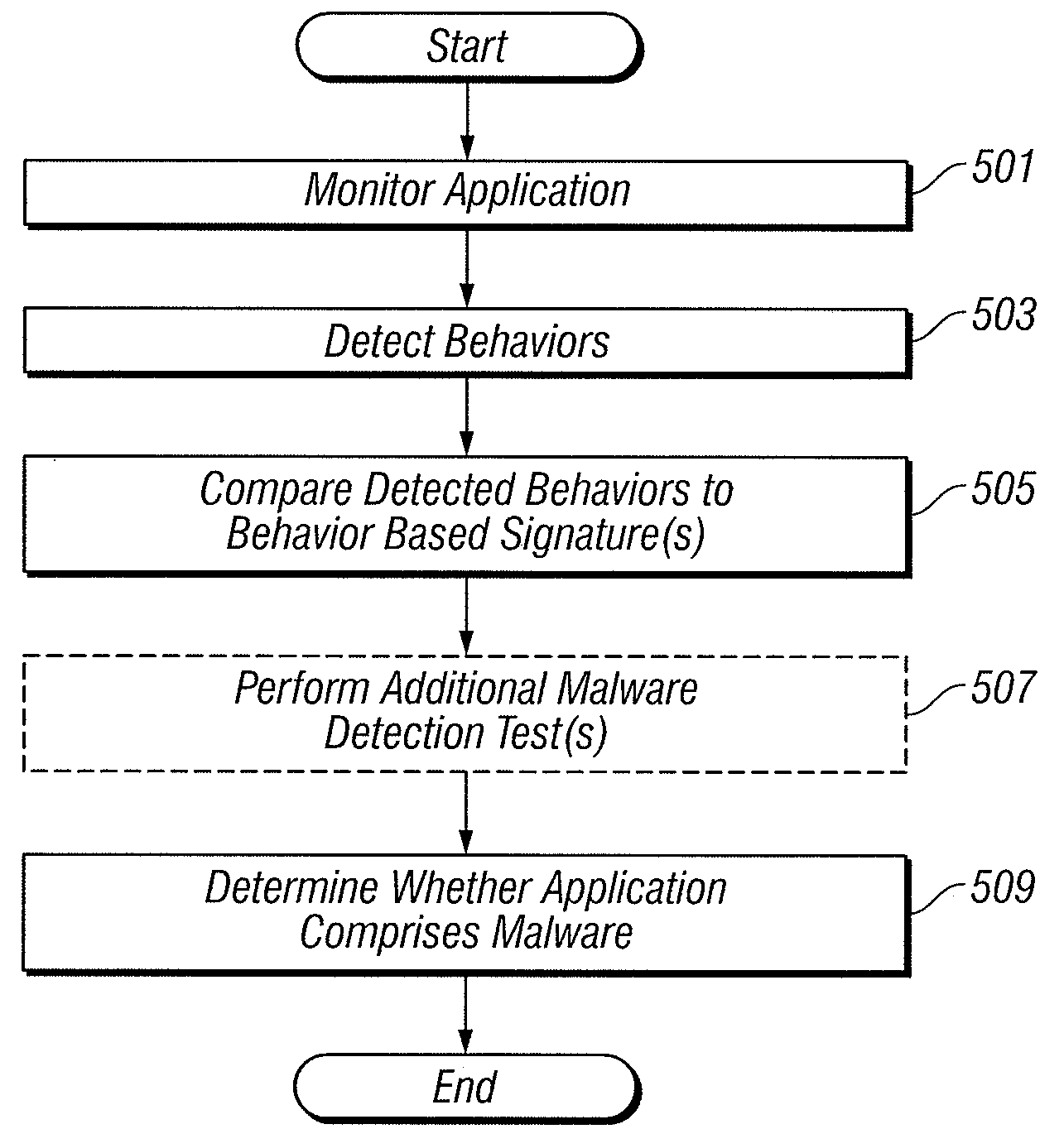
The patent describes a system for identifying malicious applications by monitoring their behavior and detecting specific behaviors that indicate maliciousness. The system creates a signature that represents these detected behaviors, which can be used to identify instances of the application. The system also compares the detected behaviors to a black-list or white-list of signatures to determine if the application is malicious. The system can also perform additional malware detection tests, such as heuristic analysis, to make a more definitive determination. Overall, the system improves the ability to detect and prevent malicious applications from causing harm.

Problems solved by technology

However, signature based detection is easily circumvented by changing content.
Signatures have become less and less useful, as malware authors have become more sophisticated at manipulating their malware to avoid signature based detection.
As a result, a large number of ineffective malware signatures are in use.
Heuristic analysis can produce a useful result in many circumstances, but there is no mathematical proof of its correctness.
Identifications of suspected malware using heuristic analysis can never, by definition, be highly certain, as heuristic analysis only determines a likelihood of a file being clean or malicious.
The confidence in heuristic based file convictions further suffers from the fact the training set is difficult to define, and is always different than the real world set.

Method used


Image

  • Behavior based signatures
  • Behavior based signatures
  • Behavior based signatures

Examples


Embodiment Construction

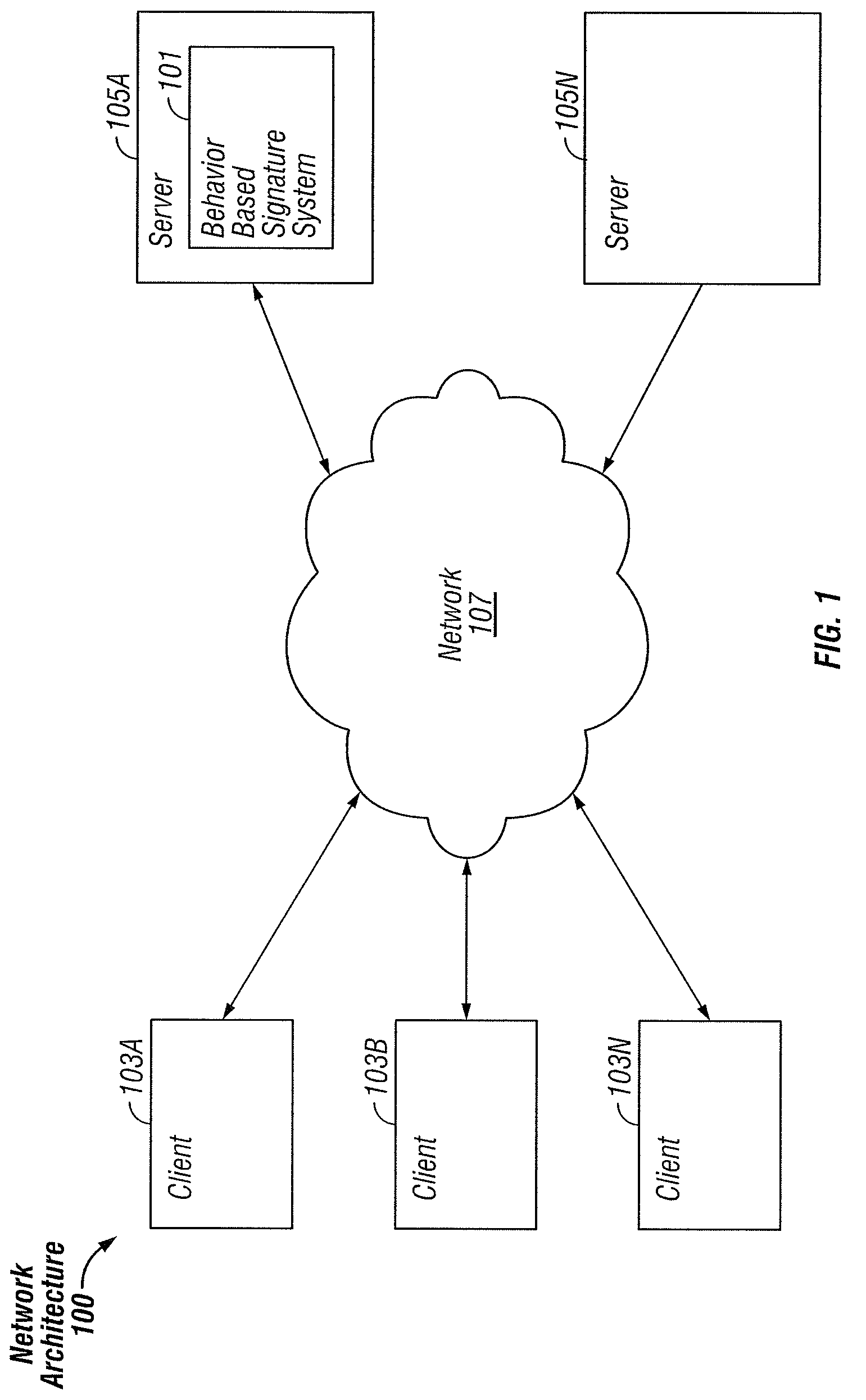
[0015]FIG. 1 is a block diagram illustrating an exemplary network architecture 100 in which a behavior based signature system 101 can be implemented. The illustrated network architecture 100 comprises multiple clients 103A, 103B and 103N, as well as multiple servers 105A and 105N. In FIG. 1, the behavior based signature system 101 is illustrated as residing on server 105A. It is to be understood that this is an example only, and in various embodiments this system 101 can be instantiated on a client 103, a server 105 or distributed between multiple clients 103 and / or servers 105.

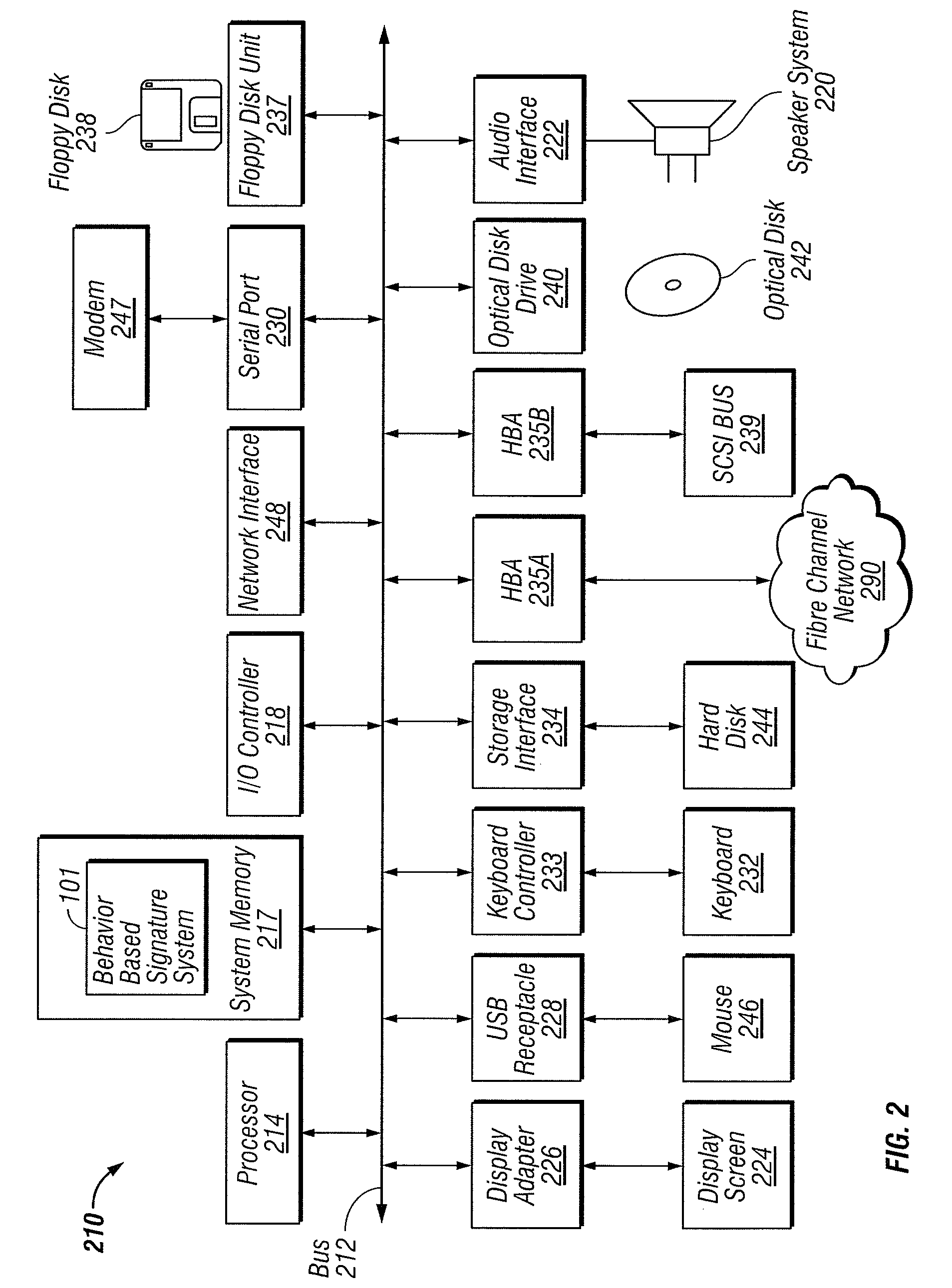
[0016]Clients 103 and servers 105 can be implemented using computer systems 210 such as the one illustrated in FIG. 2 and described below. The clients 103 and servers 105 are communicatively coupled to a network 107, for example via a network interface 248 or modem 247 as described below in conjunction with FIG. 2. Clients 103 are able to access applicants and / or data on servers 105 using, for example, a web ...


PUM


Abstract

Behavior based signatures for identifying applications are generated. An application is monitored as it runs. Specific behaviors concerning the execution of the application are detected, and a behavior based signature representing detected behaviors is created, such that the behavior based signature can be used subsequently to identify instances of the application. Behavior based signatures identifying known malicious and / or non-malicious applications can be used to determine whether other applications comprise malware. To do so, a running application is monitored, and specific behaviors concerning the execution of the application are detected. The detected behaviors are compared to one or more behavior based signatures. Responsive to whether the detected behaviors match, a behavior based signature, it can be determined whether the application comprises malware. An additional malware detection test, such as a heuristic analysis, can also be performed and used in determining whether the application comprises malware.

Description

TECHNICAL FIELD[0001]This disclosure pertains generally to computer security, and more specifically to generating behavior based signatures, and using behavior based signatures to identify malware.BACKGROUND[0002]Software exists to detect (and thus eliminate) malware (e.g., viruses, worms, Trojan horses, spyware, etc.). Such software typically works by using either static bit signatures and / or heuristics to identify malware. Static bit signature based malware detection involves identifying a specific bit-level pattern (signature) in known malware. Files are then scanned to determine whether they contain this signature. When malware is identified using static file signatures, the certainty of the conviction is high. However, signature based detection is easily circumvented by changing content. Signatures have become less and less useful, as malware authors have become more sophisticated at manipulating their malware to avoid signature based detection. For example, malware authors now...

Claims


Application Information

Patent Timeline
Patent Type & Authority Patents(United States)
IPC IPC(8): G06F21/00
CPCG06F21/566G06F21/00
Inventor GLICK, ADAMSMITH, SPENCER DALEGRAF, NICHOLAS ROBERT
Owner CA TECH INC
Learn More