Conductive connection for track-riding patient hoists

a technology for connecting cables and patient hoists, which is applied in the field of hoists, can solve problems such as difficulty in restoring the functionality of the hoist, inoperable batteries and hoists, and sometimes thwarted return-to-charger features

Active Publication Date: 2014-04-22
ARJOHUNTLEIGH MAGOG
View PDF11 Cites 13 Cited by
  • Summary
  • Abstract
  • Description
  • Claims
  • Application Information

AI Technical Summary

Benefits of technology

[0006]The hoist trolley 106 has opposing right and left trolley sides 120 (with only the right Side being visible in FIG. 1), and a contact carrier channel 122 (best seen in FIG. 2, provided on an insert 124 received within the hoist trolley 106) extends between the right and left trolley sides 120. A contact carrier 126 is fit within the contact carrier channel 122, and the contact carrier 126 includes the trolley contacts 118 (FIG. 3) thereon so that the trolley contacts 118 extend outwardly from the opposing sides of the contact carrier 126. The contact carrier 125 is movable within the contact carrier channel 122 so mat it may move in at least one dimension with respect to the hoist trolley 106 and hoist 102, namely, in the lateral (rightward / leftward) direction. Preferably, the contact carrier channel 122 is dimensioned such that its bounds (inner perimeter) are at least slightly greater than the bounds (outer perimeter) of the contact carrier 126, so that the contact carrier 126 may also move at least vertically within the hoist trolley 106. When the hoist trolley 106 is installed to ride on the track 108 (see particularly FIG. 3), the contact carrier 126 is situated between the track sides 110 with the trolley contacts 118 extending into contact with the track conductors 116. The trolley contacts 118 are in conductive communication with contact connectors 128, which can in turn be connected to hoist connectors 130 (see FIG. 1) which communicate power to the hoist 102. Thus, power supplied to the track conductors 116 (see FIG. 3) is in turn communicated to the trolley contacts 118, and then in turn to the contact connectors 128, the hoist connectors 130 (FIG. 1), and the hoist 102, whereby a hoist 102 riding along the track 108 may receive power at various locations along the track 108. The contact carrier 126, which is only restrained to the hoist trolley 106 and hoist 102 by the inner bounds of the contact carrier channel 122 (and by the flexible connection between the contact connectors 128 and hoist connectors 130, see FIG. 1), is therefore urged along the track sides lift by the hoist trolley 106, but is displaceable with respect to the hoist trolley 106 as the hoist trolley 106 rides between the track sides 110 so that the trolley contacts 118 may always remain in conductive communication with the track conductors 116. This conductive communication is also assisted by biasing the trolley contacts 118 elastically outwardly from the contact carrier 126 sides, as by the springs 132 shown in FIGS. 2 and 3, so that the trolley contacts 118 remain in contact with the track conductors 116. Because the contact carrier 126 displaces between the track sides 110 to follow their contours (and since the trolley contacts 118 are elastically biased into contact with the track conductors 116), the contact problems that may arise as the hoist trolley 106 and hoist 102 travel about the track 108 are at least substantially avoided.
[0008]As another example, upper contact covers 136 (see FIGS. 2-3) may be provided to extend outwardly from the contact carrier 126 above the trolley contacts 118, with the upper contact cover 136 riding above and closely adjacent to the track sides 110 so that the track sides 110 urge the upper contact covers 136 (and thus the contact carrier 126 and trolley contacts 118) into proper conductive alignment as the hoist trolley 106 and contact carrier 126 travel along the track 108. Each upper contact cover 136 preferably includes a first upper contact cover portion 138 extending outwardly from the hoist trolley 106 above and closely adjacent to one of track floors 112, and a second upper contact cover portion 140 extending upwardly from the first upper contact cover portion 138 closely adjacent to one of the track walls 114. The second upper contact cover portion 140 usefully helps to guide the contact carrier 126 between the track sides 110, while the first upper contact cover portion 138 assists in preventing detritus from falling between the trolley contacts 118 and track conductors 116. Lower contact covers 142 can also be provided to extend outwardly from the contact carrier 126 sides below and closely adjacent to the track sides 110 to provide further protection against foreign matter, as well as protection against inadvertent contact of the conductive components by personnel servicing the hoist 102 and hoist trolley 106.
[0009]To assist in easy maintenance of the track conductors 116, they are preferably provided as strips which are readily installable and removable within the track sides 110. Thus, as best seen in FIGS. 2-3, each track conductor 116 may bear a protruding connection tongue 144, and each track side 110 may bear a connection groove 146, with the connection tongue 144 being removably fit within the connection groove 146.

Problems solved by technology

Power may be provided to the hoists via elongated flexible cables that follow the hoists along their tracks, but these can cause difficulties owing to the length of cable needed where the hoists are to travel long distances, and owing to the desire to avoid cable slack and dangling cable.
These too pose difficulties in that users often forget to place the hoists back in their docking positions after use, leading to dead batteries and hoists which are inoperative until they are recharged (which can lead to hardships for their users).
However, such “return-to-charger” features are sometimes thwarted when objects (such as curtains, IV equipment, monitors, etc.) obstruct the return paths of the hoists.
Additionally, return-to-charger features cannot easily be implemented in “moving-track” systems such as the ones shown in U.S. Pat. No. 7,237,491, wherein the track on which the hoist rides itself rides on another track (e.g., a first track aligned along one direction is relocatable on a second track oriental perpendicularly from the first track).
In such systems, the hoist can move in a variety of directions (e.g., about a plane), but it is difficult to devise an inexpensive and reliable arrangement for having both the hoist and the track on which it rides reliably return to a charging station.
However, the arrangements used in trains and the like are not reliably and inexpensively reproducible on the scale of a hoist, since hoists use substantially smaller tracks (which tend to travel along paths having substantially sharper radii of curvature than train tracks and the like).
A key difficulty is in maintaining a reliable conductive connection between the trolley and track, particularly when the trolley travels about a curve in the crack; at this time, the contacts between the trolley and track are more likely to disengage, causing loss of power to the trolley in hoist systems.

Method used


Image

  • Conductive connection for track-riding patient hoists
  • Conductive connection for track-riding patient hoists
  • Conductive connection for track-riding patient hoists

Examples


Embodiment Construction

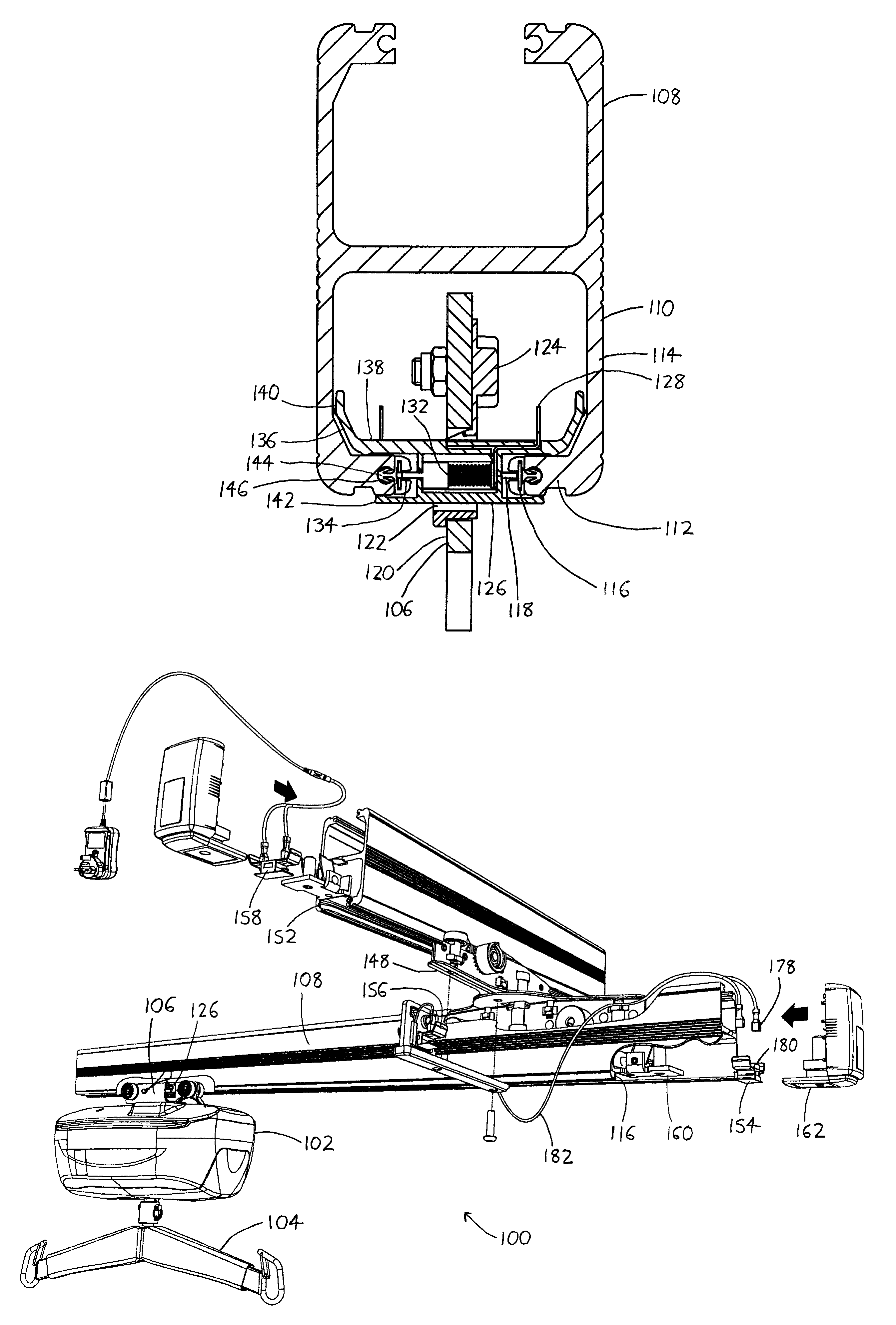
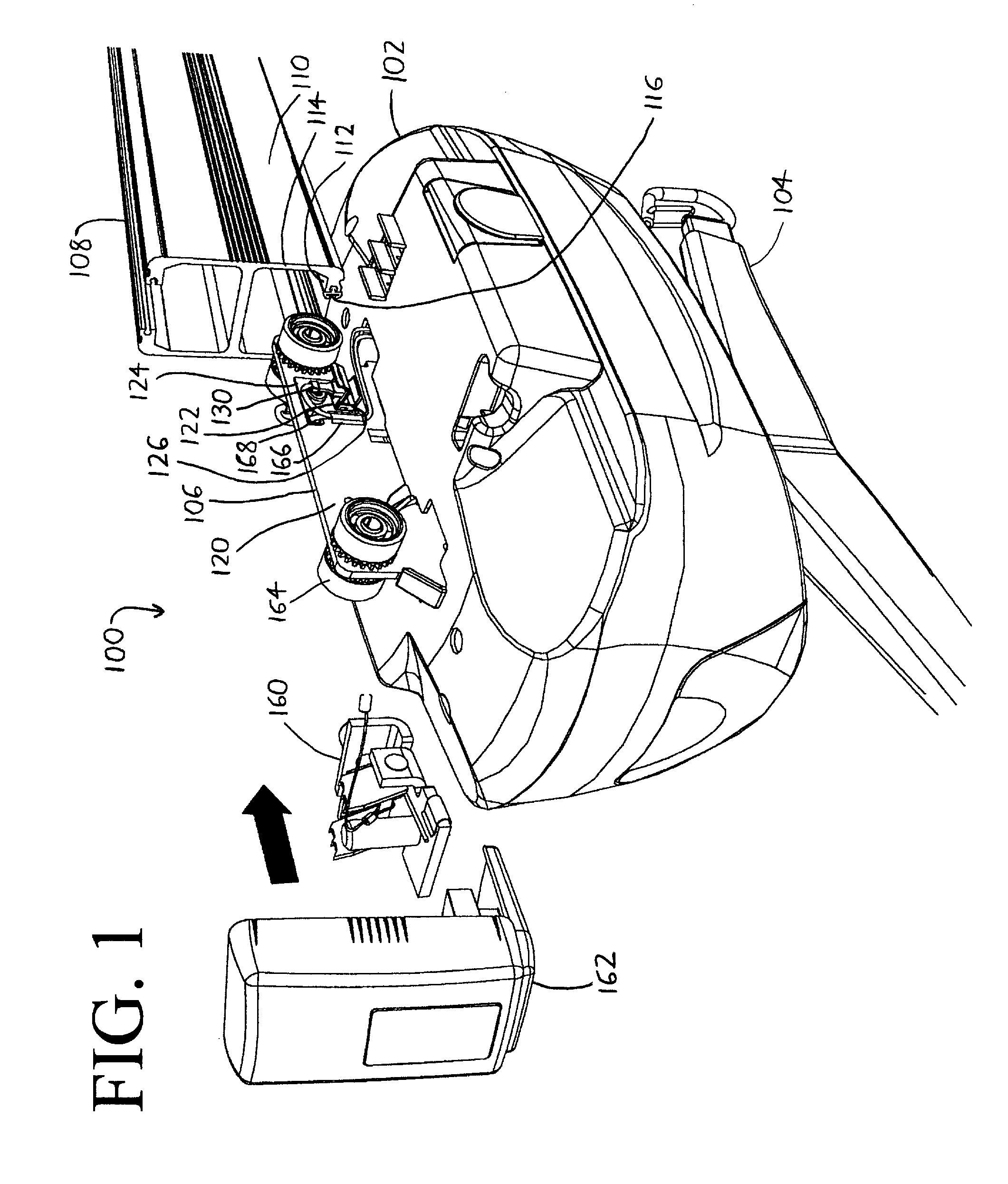
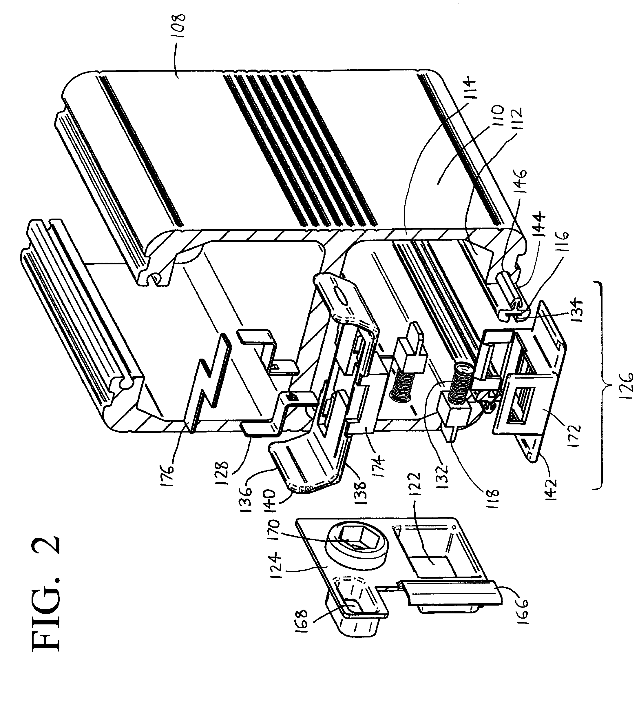
[0016]Expanding on the discussion above, the hoist 102 and track 108 illustrated throughout the drawings are adapted from the KWIKtrack and hoist system of BHM Medical Inc. (Magog, QC, Canada), which is available with a number of different track and hoist configurations. The exemplary track 108 illustrated throughout the drawings is configured similarly to a pair of C-channels which are joined with their mouths facing in opposing directions, as best seen in FIG. 3. Usefully, some versions of the KWIKtrack track, already include the connection grooves 146, which can be used to receive the connection tongues 144 of the track conductors 116 as previously described. Thus, the track 148 is readily constructed by simply installing the track conductors 116 therein. Once the track conductors 116 are installed within the track 108, the hoist trolley 106 may be installed on the track 108 by slipping the hoist trolley 106 between the track sides 110 (as illustrated in FIG. 1). At the same time...


PUM


Abstract

A patient hoist is provided on a trolley which tides along a track, with the hoist being powered by a conductor extending along the track. A contact carrier is loosely fit within the trolley, and it bears a contact which elastically biased against the track conductor, with die contact being in electrical communication with the hoist: The contact carrier is tree to laterally displace with respect to the trolley so that it (and its contact) follows the contour of the track, with the contact remaining in electrical communication with the track conductor.

Description

FIELD OF THE INVENTION[0001]This document concerns an invention relating generally to hoists which ride on ceiling-mounted or other tracks to various locations to lift or convey patients or equipment, and more specifically to hoists of this nature which require electric power supply at various locations along the track.BACKGROUND OF THE INVENTION[0002]Hoists which ride on ceiling-mounted or other tracks are commonly used in hospitals and other care centers, as well as in the homes of those with mobility impairments, to convey people and / or equipment to different areas (e.g., from a bed to a bathroom). Examples of such hoists are provided, for example, in U.S. Pat. No. 7,237,491 to Faucher et al., International (PCT) Patent Appln. Publication WO 88 / 09159, and in other patents cited in (and citing to) these references. Such hoists are usually electrically-powered, and they may ride on the tracks via manually-driven trolleys, or trolleys which are themselves electrically driven to assi...

Claims


Application Information

Patent Timeline
Patent Type & Authority Patents(United States)
IPC IPC(8): A61G7/10
CPCA61G7/1042B66C7/08
Inventor FAUCHER, MARTINMOLINAR, MICHAELCORRIVEAU, MICHAELPATRY, JOCELYN
Owner ARJOHUNTLEIGH MAGOG
Why Eureka
Try Eureka