Pipe bursting apparatus

a pipe bursting and apparatus technology, applied in mechanical apparatus, pipe laying and repair, sewer pipelines, etc., can solve the problems of large equipment, physical difficulties in the handling of such equipment, significant materials and manufacturing costs, etc., and achieve the effect of low cost, light weight and convenient us

Active Publication Date: 2014-04-22
TRIC TOOLS INC
View PDF21 Cites 15 Cited by
  • Summary
  • Abstract
  • Description
  • Claims
  • Application Information

AI Technical Summary

Benefits of technology

[0008]The foregoing needs are met by the apparatus of the invention. Several features are employed which act in a novel combination to provide a robust apparatus of relatively light weight and low cost, which is easy to use, and is capable of operating at relatively low hydraulic pressures. In particular, the apparatus of the invention comprises a pair of hydraulic cylinders, each having a cylinder rod projecting from opposite ends of the cylinder. The cylinders are mounted substantially parallel with each other to extend substantially perpendicularly from a reaction plate, with the adjacent projecting ends of the cylinder rods being secured, respectively, in mating recesses in the reaction plate. At their opposite ends, the cylinder rods are similarly secured, each in a respective mating recess in a pulling bridge. The pulling bridge is equipped with a cable gripper which secures the cable during a pulling stroke and which allows the cable to slide through it during the recovery stroke. The reaction plate is formed with a wide slot therein through which the cable passes during the pulling process and through which the cable may be passed sideways during set up. The cylinders are positioned asymmetrically with respect to the slot so as to maximize the lateral distance between them. A holding bridge is also provided spanning the slot in the reaction plate, and is removably secured to the reaction plate. The holding bridge supports a second cable gripper aligned with the cable to hold the cable in place during the recovery stroke. At the end of the pulling process, the holding bridge may be removed to enable the mole to be pulled through the slot in the resistance plate far enough to expose the replacement pipe. This eliminates the need for further excavation to expose the replacement pipe.

Problems solved by technology

Still, apparatus for pipe bursting in smaller applications remains relatively large, heavy, and complex.
As a consequence, there are physical difficulties in the handling of such equipment, and significant costs in materials and manufacturing.
Also, because of the high forces required in the pulling process, high pressure hydraulics were typically employed, further adding to the manufacturing cost.

Method used


Image

  • Pipe bursting apparatus
  • Pipe bursting apparatus
  • Pipe bursting apparatus

Examples


Embodiment Construction

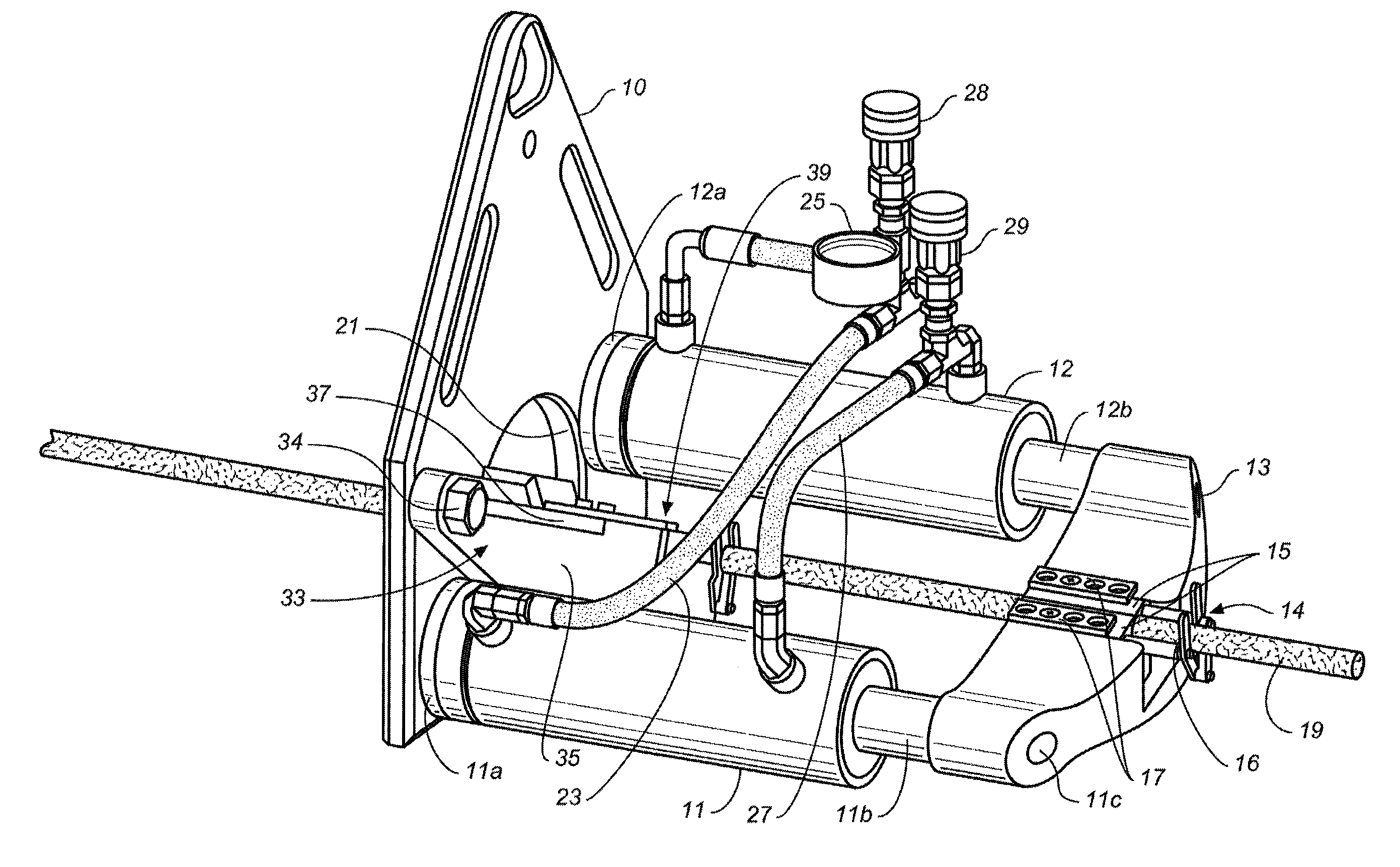
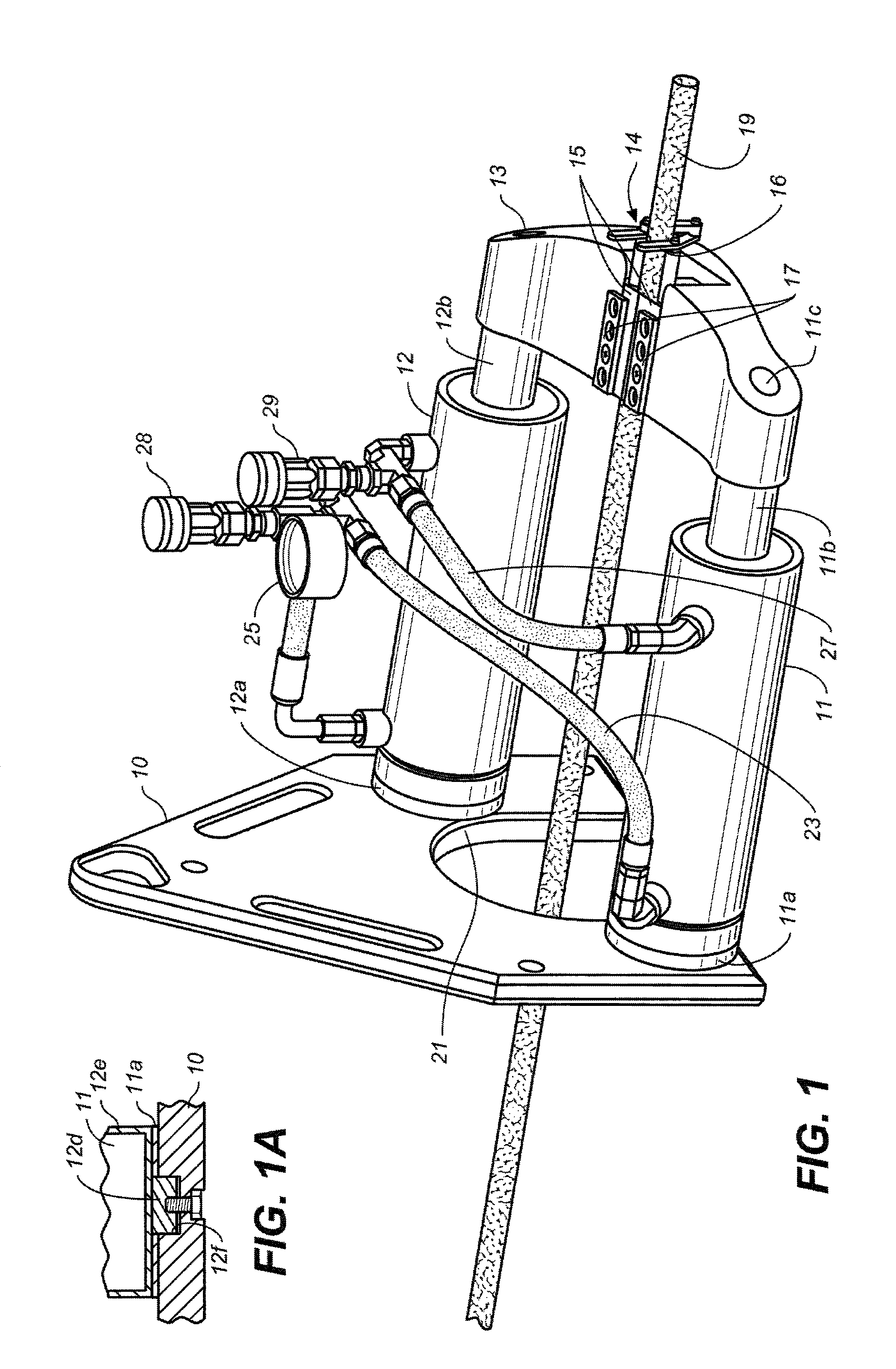
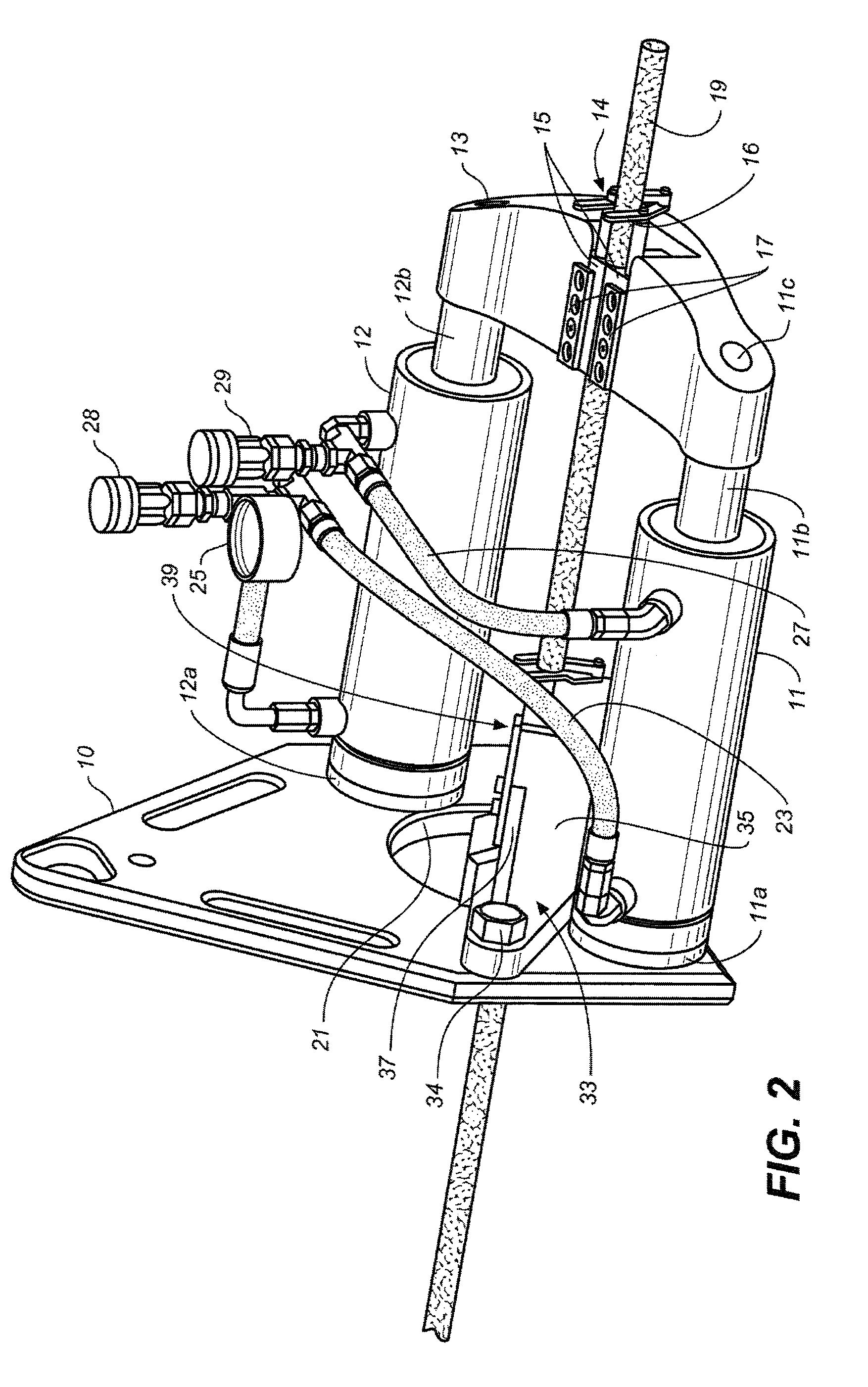
[0013]Referring to FIGS. 1 and 2, a preferred form of the apparatus of the invention is depicted. A reaction plate 10, also referred to as a resistance plate, preferably 18 to 24 inches wide, roughly the same height, and one to two inches thick is shown. It is also preferred that the reaction plate 10 be steel or comparable material. The reaction plate is positioned in a pit at one end of the segment of pipe to be replaced to bear against the wall of the pit from which the segment typically emerges. Timbers or equivalent materials may be placed between the reaction plate and the pit wall as desired to distribute the load. In any case, the reaction plate supports the other components of the apparatus as will be described. As shown, the reaction plate may be provided with openings, not numbered, for ease of handling and reduction of weight.

[0014]The reaction plate 10 is also provided with a further opening or slot 21 so as to allow a pulling cable 19 to pass through the reaction plate...


PUM


Abstract

Apparatus for replacing underground pipe is described, including a resistance plate from which a pair of hydraulic cylinders extend perpendicularly in parallel with each other. The cylinders operate cyclically with a pulling bridge having a cable gripper to provide a sequence of pulling strokes to a cable pulling a mole. The mole pulls a replacement pipe behind it through the old pipe, which has been burst, slit, or otherwise expanded by the mole. The resistance plate is provided with a slot, and the cylinders are positions such as to allow the mode to be pulled substantially completely into the apparatus. A holding bridge is releasably mounted spanning the slot in the reaction plate to position a second cable gripper for holding the cable on return stroke of the pulling bridge. The holding bridge may be removed at the end of the pulling operation to accommodate the mole.

Description

CROSS REFERENCE TO RELATED APPLICATION[0001]This application claims the benefit of U.S. Provisional Application No. 61 / 458,981 filed Dec. 3, 2010, the entirety of which is hereby incorporated by reference.FIELD OF INVENTION[0002]This invention relates to the replacement of underground pipe by the use of so called pipe bursting. More particularly, the invention relates to an improved apparatus for replacing underground pipe by bursting or slitting the pipe in situ while pulling a replacement pipe into substantially the same position.BACKGROUND[0003]Pipe bursting is a known technique for replacing underground pipe, such as sewer, water and gas lines, without having to dig a trench to remove the old pipe and position a new one. In pipe bursting, a bursting head or mole is pushed or pulled through the old pipe to burst or slit the old pipe while, usually concurrently, feeding a replacement pipe into position. The replacement pipe is typically flexible and is preferably high density poly...

Claims


Application Information

Patent Timeline
Patent Type & Authority Patents(United States)
IPC IPC(8): F16L55/18
CPCF16L55/1658F16L55/18E21B7/205
Inventor CARTER, ROBERT WARDDING, ROBERT
Owner TRIC TOOLS INC
Why Eureka
Try Eureka