Medical punch

a technology of cutting edge and cutting blade, which is applied in the field of medical punches, can solve the problems of high manufacturing cost of configuring the compatible anti-tilt mechanism, inflexible replacement of cutting parts, and cutting edges that can go out of alignment when cut, and achieve the effect of limiting the displaceability of the displaceable cutting par

Active Publication Date: 2014-04-22
KARL STORZ GMBH & CO KG
View PDF13 Cites 5 Cited by
  • Summary
  • Abstract
  • Description
  • Claims
  • Application Information

AI Technical Summary

Benefits of technology

[0008]The inventive coupling of the rigid cutting part with the hollow shaft by a coupling mechanism configured on the sleeve-shaped part, for instance in the form of a bayonet connection, ensures that the inventive medical punch can be cleaned easily and thoroughly and in addition that the cutting parts can be replaced.
[0010]According to a first embodiment of the invention, it is proposed that the anti-tilt mechanism should be configured as a thrust bearing configured in the proximal area of one cutting part, for instance in the form of a bulge-type protrusion, with which the other cutting part is contiguous, thus ensuring a reciprocal stable positioning of the cutting parts with respect to one another.
[0012]It is proposed, with a third embodiment of the invention, that the anti-tilt mechanism should be composed of a sleeve surrounding both cutting parts in the proximal area. This type of configuration of the anti-tilt mechanism constitutes a particularly simple structural approach because the stable positioning of the cutting parts is achieved without particular structural adaptation of the cutting parts by the external pressure sleeve.

Problems solved by technology

These punches have thoroughly proven themselves in the art, but in practice, in particular with stamps whose cutting edges are configured at an incline of 45 degrees with respect to the instrument's longitudinal axis, the cutting edges can go out of alignment when the cutting edges are slid into the punching or closing position.
The disadvantage of this known construction is, on the one hand, the high manufacturing cost of configuring the compatible anti-tilt mechanism and, on the other hand, the inflexibility concerning replacements of the cutting parts.

Method used


Image

  • Medical punch
  • Medical punch
  • Medical punch

Examples


first embodiment

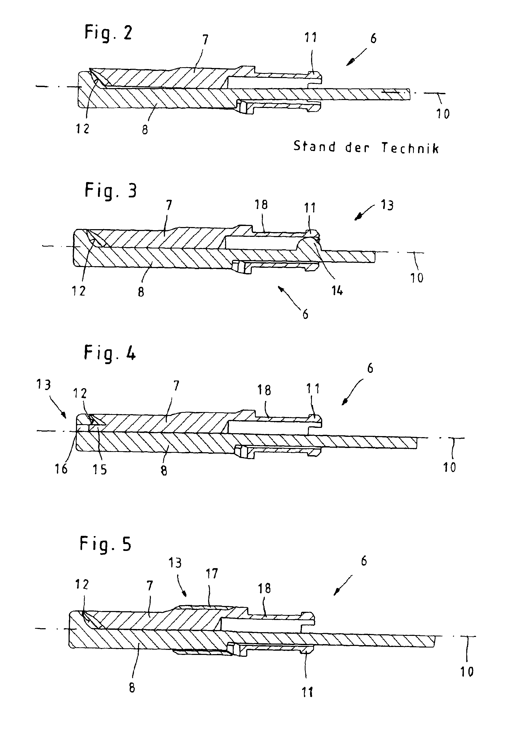
[0032]In the first embodiment shown in FIG. 3, the anti-tilt mechanism 13 is configured as a thrust bearing 14 in the form of a bulge configured in the proximal area on the displaceable cutting part 1, with which the rigid cutting part 7 is contiguous and thus the axially parallel alignment of the cutting parts 7 and 8 to one another is fixed in place.

second embodiment

[0033]In the second embodiment for configuring the anti-tilt mechanism 13, shown in FIG. 4, the anti-tilt mechanism 13 is configured as a guide pin 15 that is positioned in the distal area on the rigid cutting part 7 and engages in a corresponding recess 16 in the displaceable cutting part 8 and thus fixes in place the axial parallel alignment of the cutting parts 7 and 8 to one another in the closed punch position.

third embodiment

[0034]In the third embodiment shown in FIG. 5, the anti-tilt mechanism 13 is configured as the sleeve 17 that surrounds both cutting parts 7 and 8 in the proximal area and as an external pressure sleeve fixes the two cutting parts 7 and 8 with respect to one another.

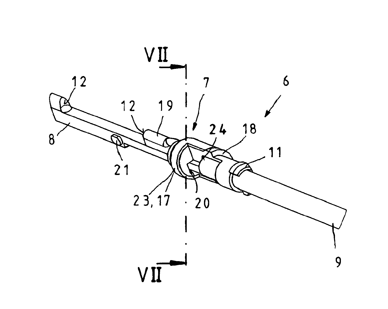
[0035]Common to all three illustrated embodiments is the fact that owing to the positioning of the anti-tilt mechanism 13 on the tool point 6, the slipping of the cutting parts 7 and 8 out of their axially parallel alignment to one another, as shown in FIG. 2 and known from the art, is prevented, so that the operator is always guaranteed an exact and calibrated actuation of the cutting parts 7 and 8 of the medical punch 1.

[0036]As can further be seen from FIGS. 3 through 6, the rigid cutting part 7 in all embodiments consists of a sleeve-shaped proximal portion 18 that encloses the displaceable cutting part 8 and a distal punch portion 19 that is configured as a single unit with the sleeve-shaped portion 18, such that a ...


PUM


Abstract

A medical punch with a hollow shaft, a tool point that is positioned on the distal end of the shaft and includes a rigid cutting part and a cutting part that can slide with respect to the rigid cutting part, and with a handle positioned on the proximal end of the shaft, such that the displaceable cutting part and the handle are operatively connected with one another by a push / pull device that is displaceably mounted in the hollow shaft and an anti-tilt mechanism is positioned on the tool point to stabilize the cutting parts in their axially parallel alignment to one another. The rigid cutting part includes a sleeve-shaped proximal portion that encloses the displaceable cutting part and a distal punch portion configured as a single unit with the sleeve-shaped portion and that the rigid cutting part should be detachably connected with the hollow shaft by a coupling mechanism formed on the sleeve-shaped portion.

Description

CROSS-REFERENCE TO RELATED APPLICATIONS[0001]The present application claims priority of German patent application No. 10 2009 024 124.8 filed on Jun. 6, 2009.FIELD OF THE INVENTION[0002]The invention relates to a medical punch with a hollow shaft, a tool point that is positioned on the distal end of the shaft and consists of a rigid cutting part and a cutting part that can slide with respect to the rigid cutting part, and a handle positioned on the proximal end of the shaft, such that the displaceable cutting part and the handle are operatively connected with one another by a push / pull device that is displaceably mounted in the hollow shaft and an anti-tilt mechanism, which stabilizes the cutting parts in their axially parallel alignment with one another, is positioned on the tool point.BACKGROUND OF THE INVENTION[0003]Medical punches are cutting tools with a rigid cutting edge and a cutting edge that can slide with respect to the rigid cutting edge, such that the two cutting edges ...

Claims


Application Information

Patent Timeline
Patent Type & Authority Patents(United States)
IPC IPC(8): A61B17/32
CPCA61B17/1611
Inventor OBERLAENDER, MARTINSAUER, MICHAELBACHER, UWESTAEHLER, MICHAEL
Owner KARL STORZ GMBH & CO KG
Why Eureka
Try Eureka