Energy storage aerodynamic braking device and method

a technology of aerodynamic braking and energy storage, which is applied in the direction of energy-efficient board measures, emergency apparatus, transportation and packaging, etc., can solve the problems of increasing fuel consumption, reducing speed, and loss of efficiency,

Inactive Publication Date: 2014-04-29
AIRBUS OPERATIONS (SAS)
View PDF15 Cites 6 Cited by
  • Summary
  • Abstract
  • Description
  • Claims
  • Application Information

AI Technical Summary

Benefits of technology

[0024]Advantageously, the sampling of energy from the kinetic energy of the vehicle is used for producing a deceleration of the vehicle and for avoiding or limiting the use of other braking means.
[0025]Advantageously, the intensity and direction of the aerodynamic braking force generated during the step of utilization of energy are modulated for matching the desired deceleration, and the aerodynamic braking means are used for generating a passive aerodynamic drag which makes it possible to avoid or to limit the utilization of specific airbrakes.
[0039]To minimize the impact of the device on the vehicle aerodynamics, the device includes means for storing energy-generating elements or aerodynamic braking forces generating means in contact with the aerodynamic flow when they are used, in order to reduce the aerodynamic drag when they are not used.

Problems solved by technology

The drag of airplanes is normally considered as a defect which must be fought since the drag is opposed to the forward motion of the airplane and increases the consumption of fuel.
However, there are particular times during the flight of a plane, when it is useful to increase the drag so as to decelerate more quickly than under the simple effect of the ordinary drag of the airplane or in order to avoid an excessive acceleration during a descent.
The problem entailed in this braking means is the loss of efficiency when speed is reduced.
Although they are largely used on civil planes, such means have numerous defects.
Thrust inverters 5 used on reactors are complex, heavy and expensive to produce as well to exploit.
In addition to the mass penalty they represent for the airplane, they reduce the performances of the motor in normal operation mode, because of the inevitable imperfections of such devices which induce aerodynamic drags and load losses which entail excessive consumptions.
Braking systems of the wheels 4 are of a limited efficiency, when the runway is contaminated by water, snow or ice and their utilization causes brakes and tires friction elements to wear and so these must be replaced all the more frequently when brakes are used intensively.

Method used


Image

  • Energy storage aerodynamic braking device and method
  • Energy storage aerodynamic braking device and method
  • Energy storage aerodynamic braking device and method

Examples


Embodiment Construction

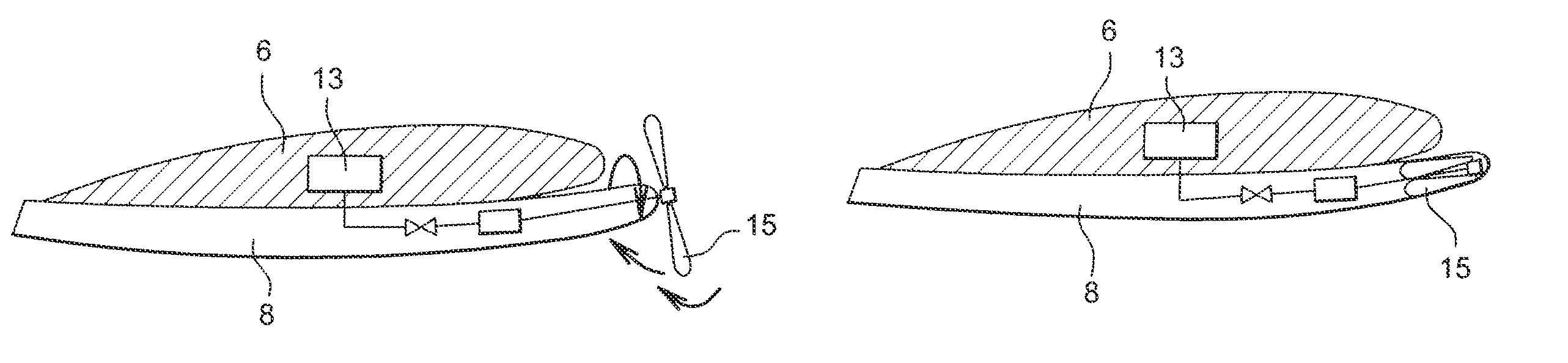
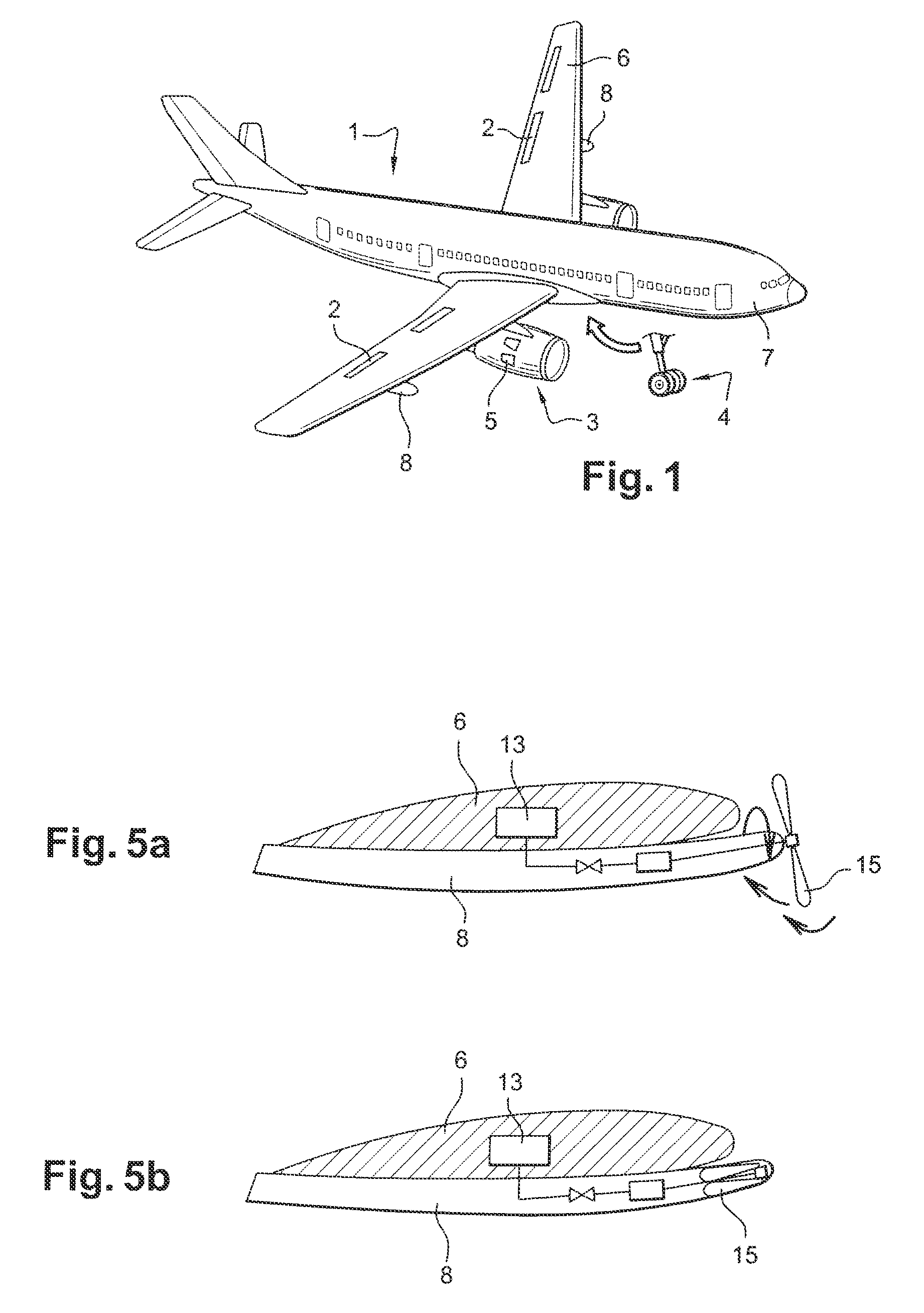
[0046]A method according to the invention consists of a first step to store an available energy aboard the plane, by sampling this energy using means and during steps of the flight during which said sampling of energy from the performances of the plane is advantageous or acceptable, as regards degradation, and in a second step, to use the energy stored for generating an aerodynamic force opposed to the forward motion speed of the plane.

[0047]In a first implementation of the method, the stored energy is sampled from the kinetic energy of the plane 1 and is generated by using speed V of the plane 1 with respect to air.

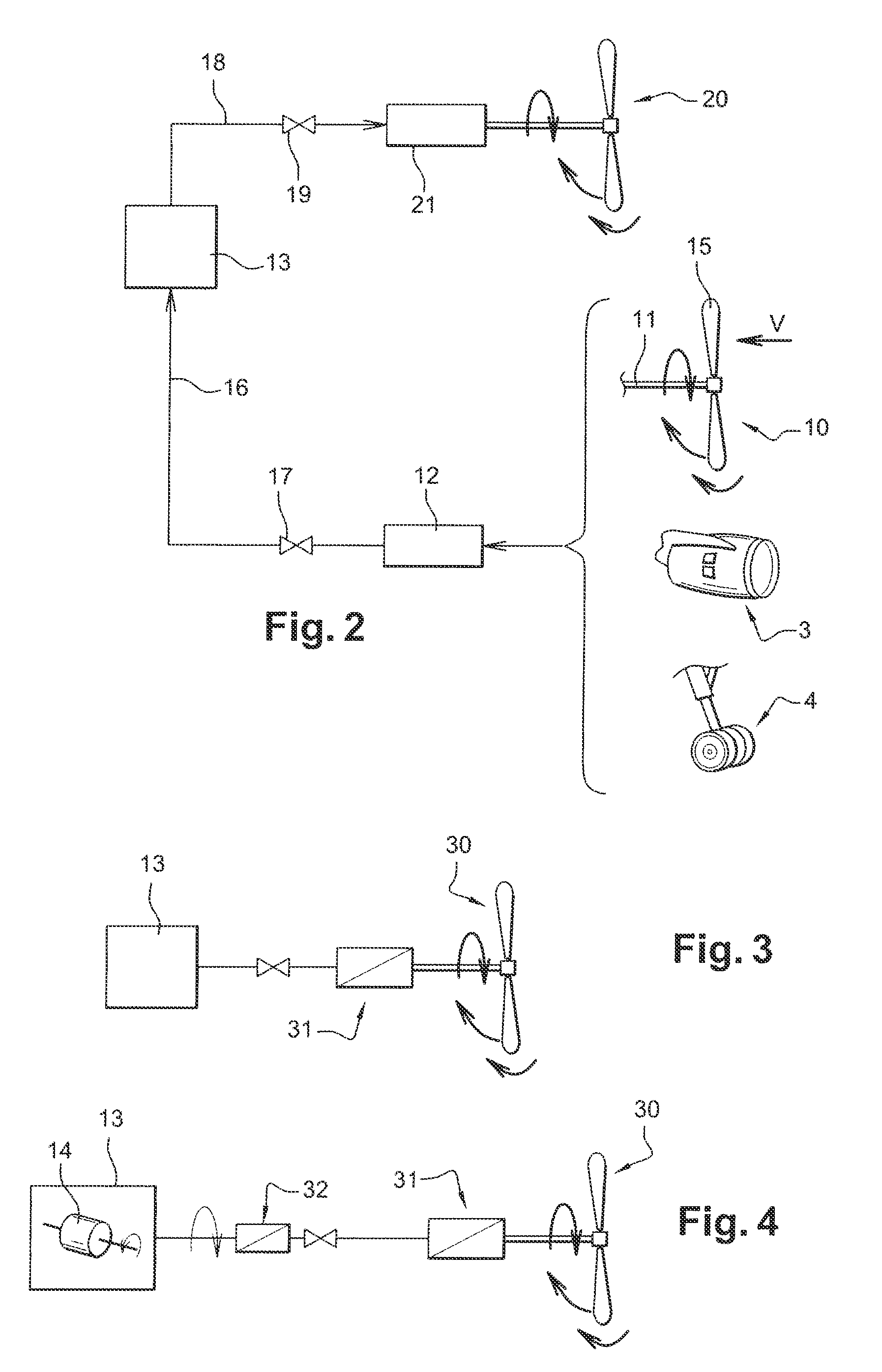
[0048]Energy is sampled using at least one propeller 10 integral with the plane 1 and operated in a so-called wind energy mode, i.e. the propeller is driven by the relative speed of the flow caused by the displacement of the plane 1 in air.

[0049]The rotation of the shaft 11 of the propeller 10 is connected to the rotating shaft of a generator 12, so that the generator 12...


PUM


Abstract

In order to generate an efficient aerodynamic braking force, whatever the speed of a vehicle such as an airplane flying in the air, the method includes a step for the production of energy by the vehicle, a step of storage of the energy produced and a step of utilization of such energy to drive a propeller which generates a force opposing the forward motion of the vehicle. Energy is produced by using the displacement of the vehicle with respect to air using a propeller driving a generator, or using the displacement with respect to the ground, using wheels driving a generator, or using generators driven by motors of the vehicle. The energy can be stored in the pneumatic, electric or kinetic form and the generation and driving means are selected according to the technology used for the storage means.

Description

CROSS-REFERENCE TO RELATED APPLICATIONS[0001]This application claims priority to International Application PCT / FR2008 / 050474 filed 19 Mar. 2008, which claims priority to French Application No. 07 53929 filed on 20 Mar. 2007, the disclosures of which are incorporated herein by reference in their entireties.BACKGROUND[0002]1. Field[0003]The aspects of the disclosed embodiments relate to the field of the control of airplane flights. More particularly, the aspects of the disclosed embodiments relate to devices intended to act on the drag force of planes generally grouped under the name of “airbrakes”.[0004]2. Brief Description of Related Developments[0005]The drag of airplanes is normally considered as a defect which must be fought since the drag is opposed to the forward motion of the airplane and increases the consumption of fuel.[0006]However, there are particular times during the flight of a plane, when it is useful to increase the drag so as to decelerate more quickly than under th...

Claims


Application Information

Patent Timeline
Patent Type & Authority Patents(United States)
IPC IPC(8): B64C9/32B64D41/00
CPCY02T50/44B64C25/36B64D41/007B64C25/405Y02T50/823Y02T50/40Y02T50/50Y02T50/80
Inventor BELLEVILLE, MATHIEU
Owner AIRBUS OPERATIONS (SAS)
Why Eureka
Try Eureka