Optical fixing device and image forming apparatus
an image forming apparatus and fixing device technology, applied in the field of optical fixing devices and image forming apparatuses, can solve the problems of insufficient fix level, insufficient high gloss level, and limitation of high speed fixation, so as to improve image smoothness, improve image fix level, and high gloss level
- Summary
- Abstract
- Description
- Claims
- Application Information
AI Technical Summary
Benefits of technology
Problems solved by technology
Method used
Image
Examples
example 1
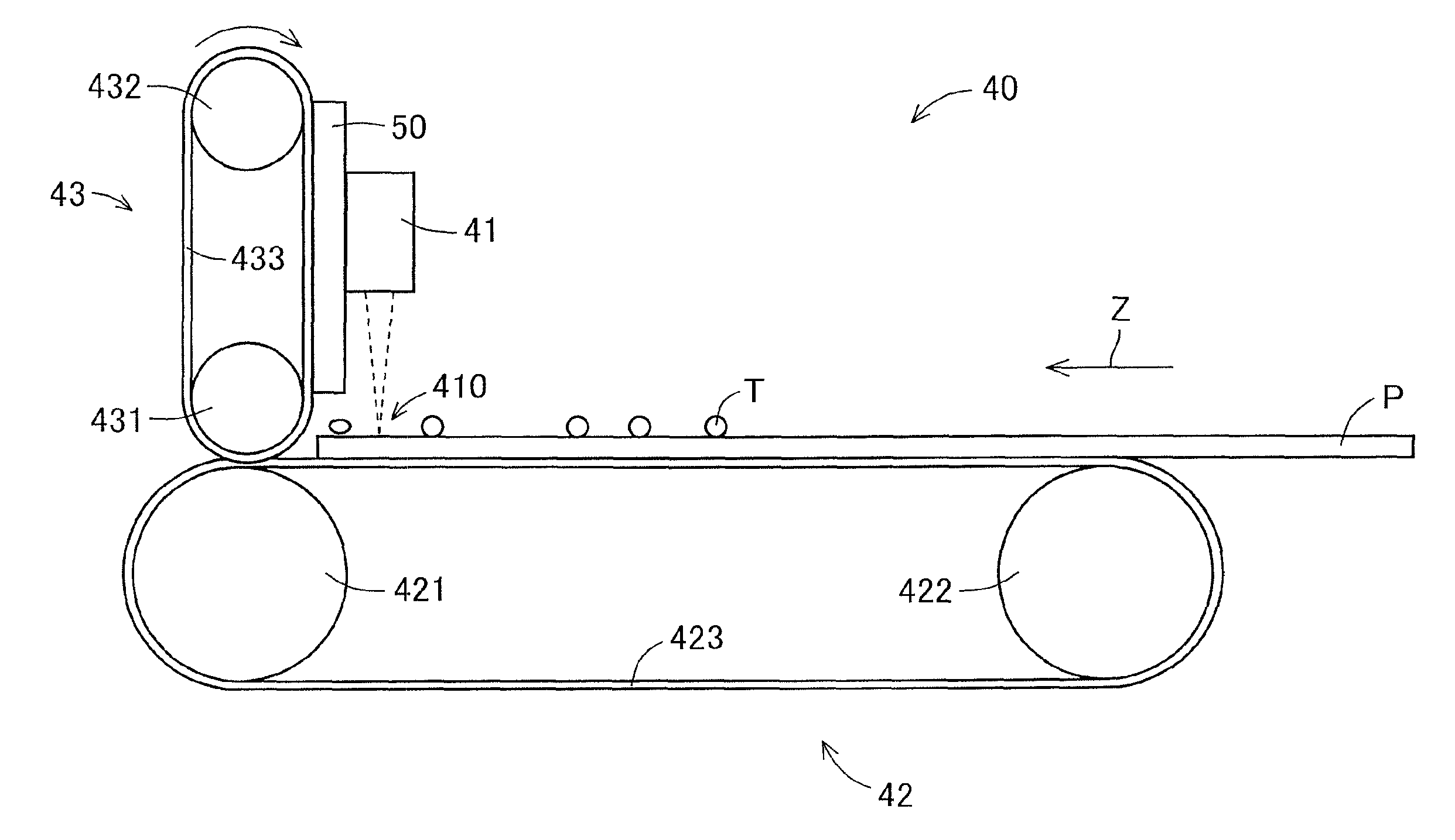
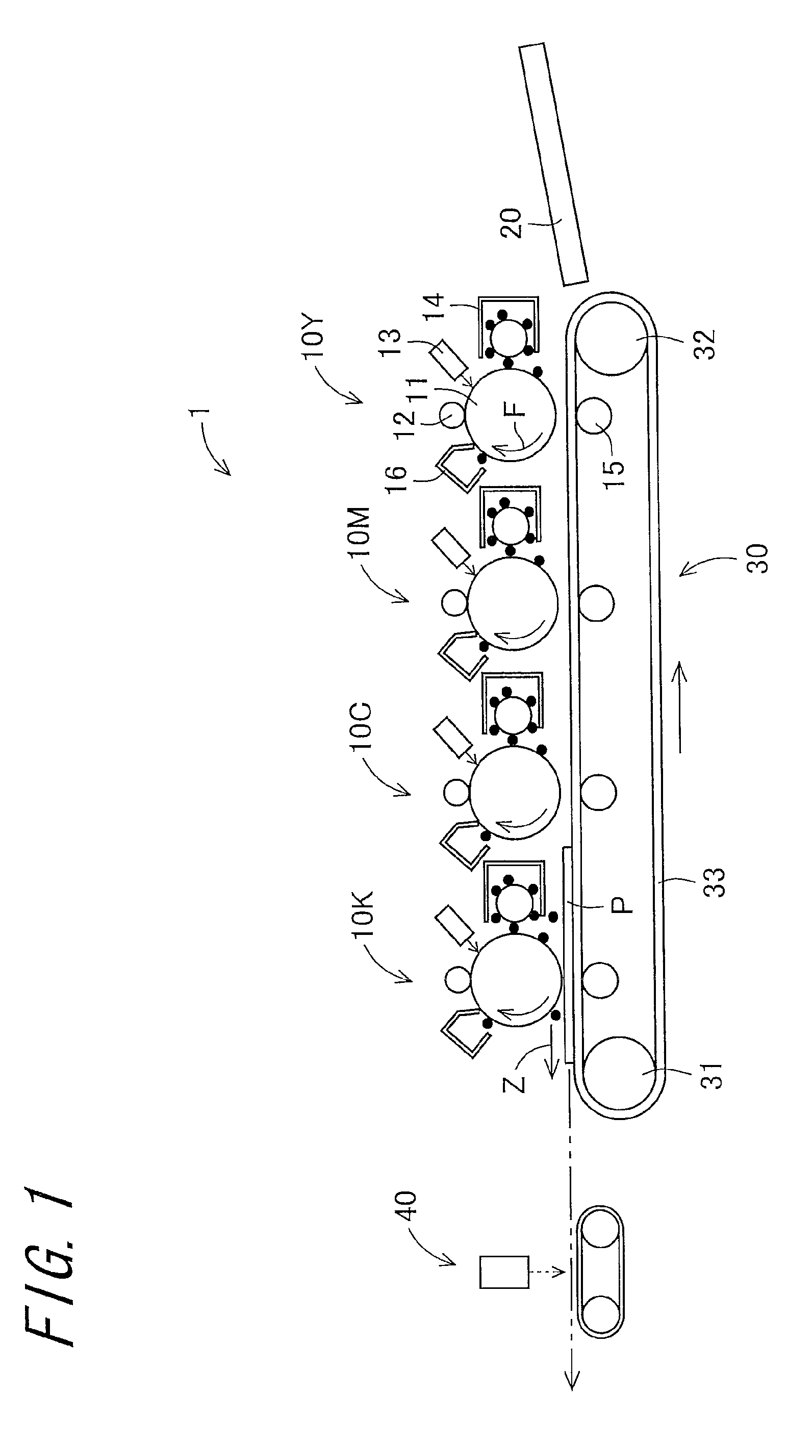
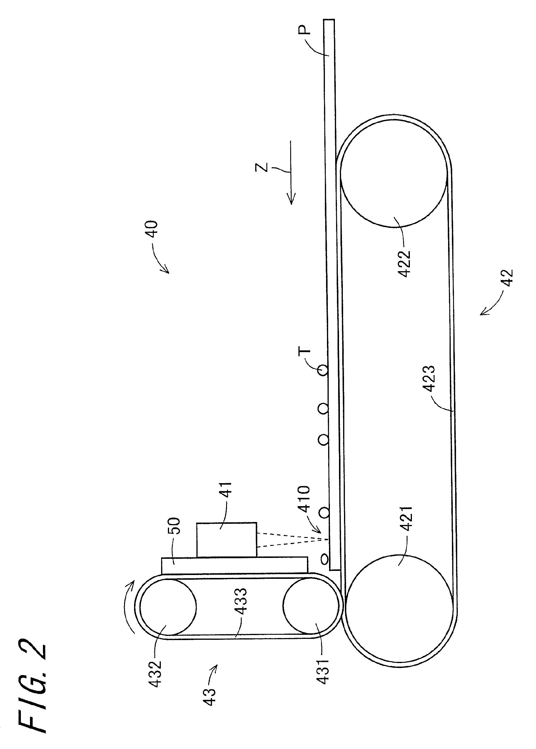
[0092]The image forming apparatus comprising the optical fixing device 40 of FIG. 2 was used. Specifically, in Example 1, an image forming apparatus comprising an optical fixing device with a pressurizing section that is disposed on a downstream side in a recording sheet conveyance direction with respect to a laser irradiation section was disposed, and the optical fixing device was configured that a pressure belt of the pressurizing section and a ceramic substrate of the laser irradiation section are disposed in pressure-contact with each other with a high thermal conducting member interposed therebetween.
[0093]To the laser irradiation section, 600 W of electricity was inputted to fix an unfixed toner image (toner attachment amount: 0.6 mg / cm2) to a recording sheet at process speed of 220 mm / sec.
[0094]Note that, since a light conversion efficiency of the laser irradiation section is 50%, 300 W out of 600 W of electricity inputted to the laser irradiation section was used for irradia...
example 2
[0095]A configuration of the optical fixing device disposed in the image forming apparatus was the same as that of Example 1 except being configured that the pressurizing section was not in contact with the laser irradiation section.
[0096]To the laser irradiation section, 600 W of electricity was inputted to fix an unfixed toner image (toner attachment amount: 0.6 mg / cm2) to a recording sheet at process speed of 220 mm / sec.
[0097]Note that, since a light conversion efficiency of the laser irradiation section is 50%, 300 W out of 600 W of electricity inputted to the laser irradiation section, 300 W thereof was used for irradiation of a laser beam, and the remained 300 W became a conversion loss so that heat was dissipated from the ceramic substrate. A fan was used for cooling heat dissipated from the ceramic substrate, and electricity inputted to the fan was 150 W. Namely, in Example 2, a total energy conversion efficiency in the laser irradiation section (ratio of electricity used fo...
PUM
 Abstract
Description
Claims
Application Information
 - R&D
- Intellectual Property
- Life Sciences
- Materials
- Tech Scout
- Unparalleled Data Quality
- Higher Quality Content
- 60% Fewer Hallucinations
Browse by: Latest US Patents, China's latest patents, Technical Efficacy Thesaurus, Application Domain, Technology Topic, Popular Technical Reports.
© 2025 PatSnap. All rights reserved.Legal|Privacy policy|Modern Slavery Act Transparency Statement|Sitemap|About US| Contact US: help@patsnap.com


