Fixing apparatus

a technology of fixing apparatus and fixing end portion, which is applied in the direction of electrographic process apparatus, instruments, optics, etc., can solve the problems of affecting the temperature in the non-passing area of the sheet, and achieves the effect of suppressing the temperature rise in the non-passing area and increasing the fixability of the end portion

Active Publication Date: 2017-05-23
CANON KK
View PDF13 Cites 0 Cited by
  • Summary
  • Abstract
  • Description
  • Claims
  • Application Information

AI Technical Summary

Benefits of technology

[0007]The present disclosure increases the fixability of the end portions while suppressing temperature rise in the sheet non-passing areas. A first aspect of present disclosure is a fixing apparatus for fixing a toner image on a recording material while conveying and heating, at a nip portion, the recoding material on which the toner image has been formed, the fixing apparatus including a rotary member that includes a conductive layer, a helical coil provided inside the rotary member, a helical axis of the coil extending in a generatrix direction of the rotary member; a magnetic core provided inside the coil, the magnetic core having a shape that does not form a loop outside the conductive layer; and a back-up member that forms a nip portion together with the rotary member. The conductive layer generates heat with an electric current flowing in the conductive layer, the electric current being induced by an alternating magnetic field generated by an electric current flowing, in the coil, and

Problems solved by technology

However, in the fixing apparatus of Japanese Patent Laid-Open No 2014-026267, since the magnetic flux density decreases from the middle portion to the end portions of the magnetic core in the generatrix direction of the rotary member, the fixability at the end portions tend to decrease.
Furthermore, when attempting to increase the heat generation amount at the end portions, the temperature in the sheet non-passing areas may rise adversely.

Method used


Image

  • Fixing apparatus
  • Fixing apparatus
  • Fixing apparatus

Examples


first exemplary embodiment

1. Description of Outline Of Image Forming Apparatus

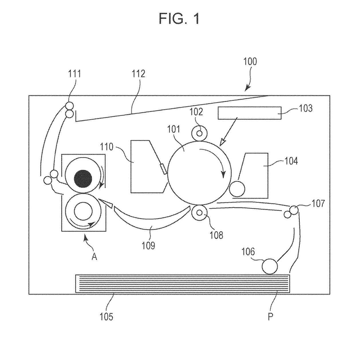
[0017]Referring to FIG. 1, an image forming apparatus according to an exemplary embodiment will be described. FIG. 1 is a cross-sectional view illustrating a schematic configuration of an exemplary printer 100 that is an electrophotographic image forming apparatus.

[0018]The image forming apparatus 100 includes a photosensitive drum 101, a charging member 102, a laser scanner 103, and a developer device 104 that serve as an image forming unit for forming an unfixed toner image on a recording material P. The image forming unit further includes a cleaner 110 that cleans the photosensitive drum 101, and a transfer member 108.

[0019]The recording materials P contained in a cassette 105 inside a main body of the image forming apparatus 100 is fed sheet by sheet with a rotation of a roller 106. With a rotation of a roller 107, the recording material P is conveyed to a transfer nip portion formed by the photosensitive drum 101 and the trans...


PUM


Abstract

A fixing apparatus for fixing a toner image on a recording material while conveying and heating, at a nip portion, the recoding material on which the toner image has been formed, the fixing apparatus including a rotary member including a conductive layer, a helical coil provided inside the rotary member, a helical axis of the helical coil extending in a generatrix direction of the rotary member, a magnetic core provided inside the helical coil, the magnetic core having a shape that does not form a loop outside the conductive layer, and a back-up member forming a nip portion together with the rotary member. In the generatrix direction, when winding pitches of the helical coil in a middle area, in end-portion areas, and in intermediate areas that are areas between the middle area and the end-portion areas are X, Y, and Z, respectively, then Y<X<Z is satisfied.

Description

BACKGROUND OF THE INVENTION[0001]Field of the Invention[0002]The present disclosure relates to a fixing apparatus included in an electrophotographic image forming apparatus.[0003]Description of the Related Art[0004]Electromagnetic induction heat generating systems are known as fixing apparatuses mounted in image forming apparatuses, such as an electrophotographic copying machine and a printer. In such fixing apparatuses, a fixing apparatus that includes a rotary member including a conducive layer, a helical coil provided inside the rotary member, and a magnetic core with ends that is provided in a helical shaped portion of the coil, in which the entire circumference of the conductive layer generates heat has been disclosed in recent years (Japanese Patent Laid-Open No. 2014-026267). The fixing apparatus distributes high-frequency current to the coil to generate a magnetic flux in a generatrix direction of the rotary member, generates heat in the conductive layer with an induced curr...

Claims


Application Information

Patent Timeline
Patent Type & Authority Patents(United States)
IPC IPC(8): G03G15/20
CPCG03G15/2053G03G2215/2035
Inventor NISHIMURA, SHIZUMA
Owner CANON KK
Why Eureka
Try Eureka