Image reading apparatus and image forming apparatus

a reading apparatus and image technology, applied in the field of image reading apparatus, can solve the problems of large driving force of the original conveying apparatus, noise generation, and inability to open and close the original pressing portion smoothly, and achieve the effect of smooth opening and closing of the original pressing portion

Inactive Publication Date: 2014-04-29
CANON KK
View PDF22 Cites 0 Cited by
  • Summary
  • Abstract
  • Description
  • Claims
  • Application Information

AI Technical Summary

Benefits of technology

[0012]The present invention provides an image reading apparatus which can smoothly open and close the original pressing portion in the image reading apparatus which uses plural driving portions to open and close the original pressing portion.
[0013]The present invention provides an image forming apparatus including an image reading apparatus which can read the original without shifting the original position to decrease the number of cases where the image is re-formed on the new sheet.
[0015]Accordingly, in the image reading apparatus of the invention, the controlling portion performs the control such that the actuation speeds of the plural driving portions are matched with each other, so that the inclination of the original pressing portion can be decreased to smoothly open and close the original pressing portion. Additionally, the vibration can be decreased to reduce the noise. Additionally, the original position is hardly shifted when the original pressing portion presses the original against the original base plate.
[0016]Accordingly, the image forming apparatus of the invention includes the image reading apparatus in which the original position is hardly shifted when the original pressing portion presses the original against the original base plate, so that the number of cases where the image is re-formed on the new sheet can be decreased to improve the image forming efficiency.

Problems solved by technology

However, in the conventional image reading apparatus, a large motor having a large driving force is required because the original conveying apparatus is opened and closed by the one motor.
Sometimes the use of the large motor locally needs a wide installation space to restrict the installation space of the motor.
Accordingly, in the image reading apparatus in which the plural motors are used, the original conveying apparatus cannot smoothly be opened and closed, or a noise is generated.

Method used


Image

  • Image reading apparatus and image forming apparatus
  • Image reading apparatus and image forming apparatus
  • Image reading apparatus and image forming apparatus

Examples


first embodiment

[0055](Image Reading Apparatus of First Embodiment)

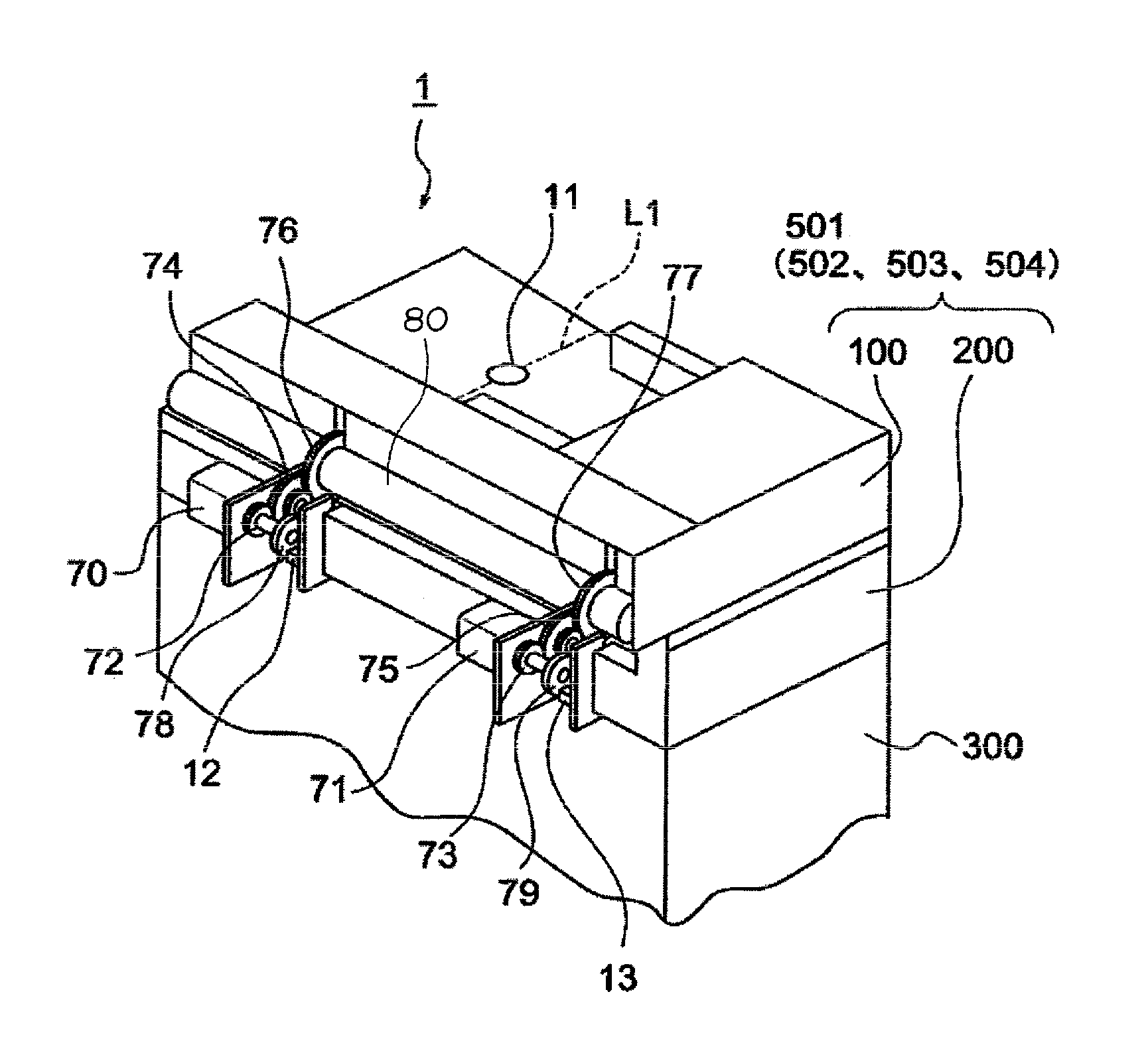
[0056]An image reading apparatus 501 according to a first embodiment is configured such that a rotation angular velocity ω2 of a motor 71 is matched with a rotation angular velocity ω1 (FIGS. 7A and 7B) of a motor 70 (FIG. 3) which opens and closes the original conveying apparatus 100.

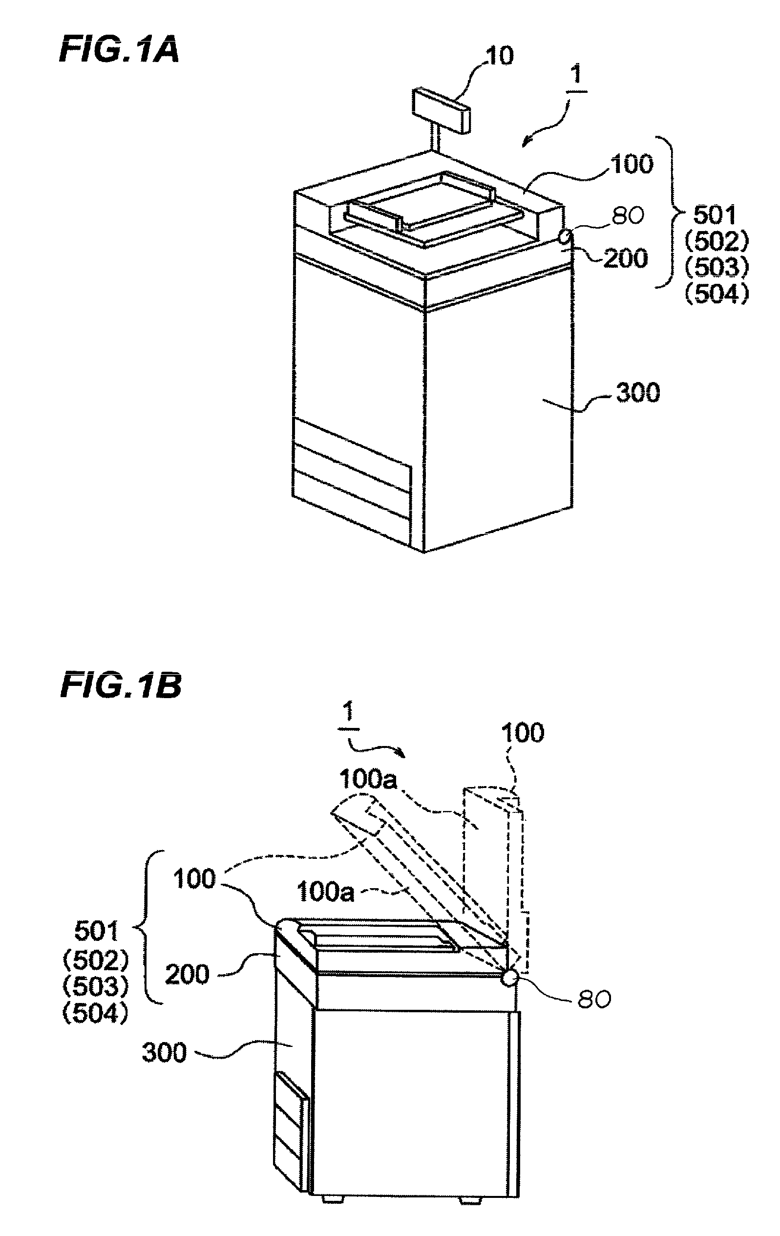
[0057]In FIGS. 1 to 3, the original conveying apparatus 100 is provided in the reading portion 200 to automatically open and close the reading portion 200. Plural motors 70 and 71 and the operation portion 10 are provided in the backside of the reading portion 200. The plural motors 70 and 71 are of the driving portion for opening and closing the original conveying apparatus 100. The stepping motors are used as the motors 70 and 71, and the stepping motors can freely change a speed and a rotation direction according to computation output of the opening and closing action controlling portion 14 (FIG. 4).

[0058]The opening and closing action controlling p...

second embodiment

[0082](Image Reading Apparatus of Second Embodiment)

[0083]The image reading apparatus 501 of the first embodiment is configured such that the rotation angular velocity ω1 of the motor 70 is matched with the rotation angular velocity ω2 of the motor 71. On the other hand, an image reading apparatus 502 according to a second embodiment is configured such that the rotation angular velocity ω1 of the motor 70 and the rotation angular velocity ω2 of the motor 71 are mutually matched with each other. Therefore, the image reading apparatus 502 of the second embodiment differs from the image reading apparatus 501 of the first embodiment in an opening and closing action controlling portion 114 and the flow of the control computation. Only the different points will be described with reference to FIGS. 8A and 8B.

[0084]FIG. 8A illustrates a block diagram for controlling the image forming apparatus and illustrates a signal flow in performing the control computation. FIG. 8B illustrates a flow ex...

third embodiment

[0097](Image Reading Apparatus of Third Embodiment)

[0098]In an image reading apparatus 503 according to a third embodiment, the rotation angular velocity ω1 of the motor 70 is matched with the rotation angular velocity ω2 of the motor 71, and the rotation angular velocity ω2 of the motor 71 is controlled in consideration of an inclination angular velocity ω3 of the original conveying apparatus 100, which is detected by the inclination detection sensor 11.

[0099]Therefore, in the image reading apparatus of the third embodiment, the variation in speed about the front-back direction axis L1 (FIG. 3) passing through the barycenter of the original conveying apparatus can be reduced in the original conveying apparatus during the opening and closing action.

[0100]FIGS. 9A and 9B illustrate the control of the image reading apparatus of the third embodiment. FIG. 9A partially illustrates a block diagram for controlling the image forming apparatus and illustrates a signal flow in performing the...


PUM


Abstract

In an image reading apparatus which uses plural motors to open and close an original conveying apparatus, the original conveying apparatus can smoothly be opened and closed.The image reading apparatus includes an original base plate on which an original is placed; an original conveying apparatus which can be opened and closed with respect to the original base plate, the original conveying apparatus pressing the original against the original base plate while closed; a reading portion which reads an image of the original pressed against the original base plate by the original pressing portion; plural motors which open and close the original conveying apparatus; plural rotary encoders which detect actuation states of the motors; and an opening and closing action controlling portion which controls the motors to match actuation speeds of the plural motors with each other based on the actuation states detected by the rotary encoders.

Description

BACKGROUND OF THE INVENTION[0001]1. Field of the Invention[0002]The present invention relates to an image reading apparatus which reads an image of an original and an image forming apparatus provided with the image reading apparatus.[0003]2. Description of the Related Art[0004]Conventionally, the image forming apparatus includes the image reading apparatus in an upper portion of a main body thereof, and the original is copied on a sheet based on information on the original image read by the image reading apparatus, thereby discharging the sheet to the outside to provide the copy of the original to a user.[0005]The image reading apparatus includes an original base plate, an original pressing portion, and an image reading portion. The original is placed on the original base plate. The original pressing portion can be opened and closed with respect to the original base plate, and the original pressing portion presses the original against an original base plate while closed. The image r...

Claims


Application Information

Patent Timeline
Patent Type & Authority Patents(United States)
IPC IPC(8): G03G15/04H04N1/00G03G15/00
CPCG03G15/605H04N1/1013H04N1/00538H04N2201/0422
Inventor MITAMURA, AKIYUKI
Owner CANON KK
Why Eureka
Try Eureka