Platen unit and liquid ejecting apparatus

a liquid ejecting apparatus and platen technology, applied in the direction of printing mechanism, power drive mechanism, printing, etc., can solve the problems of large frictional force between the medium and the platen, inability to properly eject the ink, and restricted the upper limit position of the platen, so as to achieve the effect of suppressing static electricity

Inactive Publication Date: 2014-05-06
SEIKO EPSON CORP
View PDF4 Cites 3 Cited by
  • Summary
  • Abstract
  • Description
  • Claims
  • Application Information

AI Technical Summary

Benefits of technology

[0010]When the medium enters on the platen, a front end thereof hits the platen. This arises a risk that a large frictional force is generated between the medium and the platen. However, with the above-described configuration, the platen is movable in the up-down direction on the elastic member. Therefore, the platen can move downward when the medium enters. This makes it possible to reduce the frictional force between the medium and the platen so as to suppress static electricity from being generated on the platen. In addition, after the medium has entered, a position of the platen can be returned to an original height with an elastic force of the elastic member. Moreover, since the medium is sucked through the hole, the medium can be ensured to be flat on the platen appropriately.
[0012]With this configuration, the platen moves downward when the medium enters so as to suppress static electricity from being generated. In addition, when the platen tries to return upward after the medium has entered, the upper limit position of the platen is restricted. Therefore, a distance between a head and the medium on the platen can be kept constant.
[0024]When the medium enters on the platen, a front end thereof hits the platen. This arises a risk that a large frictional force is generated between the medium and the platen. However, with the above-described configuration, the platen is movable in the up-down direction on the elastic member. Therefore, the platen can move downward when the medium enters. This makes it possible to reduce the frictional force between the medium and the platen so as to suppress static electricity from being generated on the platen. In addition, after the medium has entered, a position of the platen can be returned to an original height with an elastic force of the elastic member. Moreover, since the medium is sucked through the hole, the medium can be ensured to be flat on the platen appropriately.

Problems solved by technology

If the paper powder is adsorbed to the nozzles, the nozzles are clogged, resulting in a problem that ink is not ejected appropriately, or the like.
This arises a risk that a large frictional force is generated between the medium and the platen.
In addition, when the platen tries to return upward after the medium has entered, the upper limit position of the platen is restricted.
This arises a risk that a large frictional force is generated between the medium and the platen.

Method used


Image

  • Platen unit and liquid ejecting apparatus
  • Platen unit and liquid ejecting apparatus
  • Platen unit and liquid ejecting apparatus

Examples


Embodiment Construction

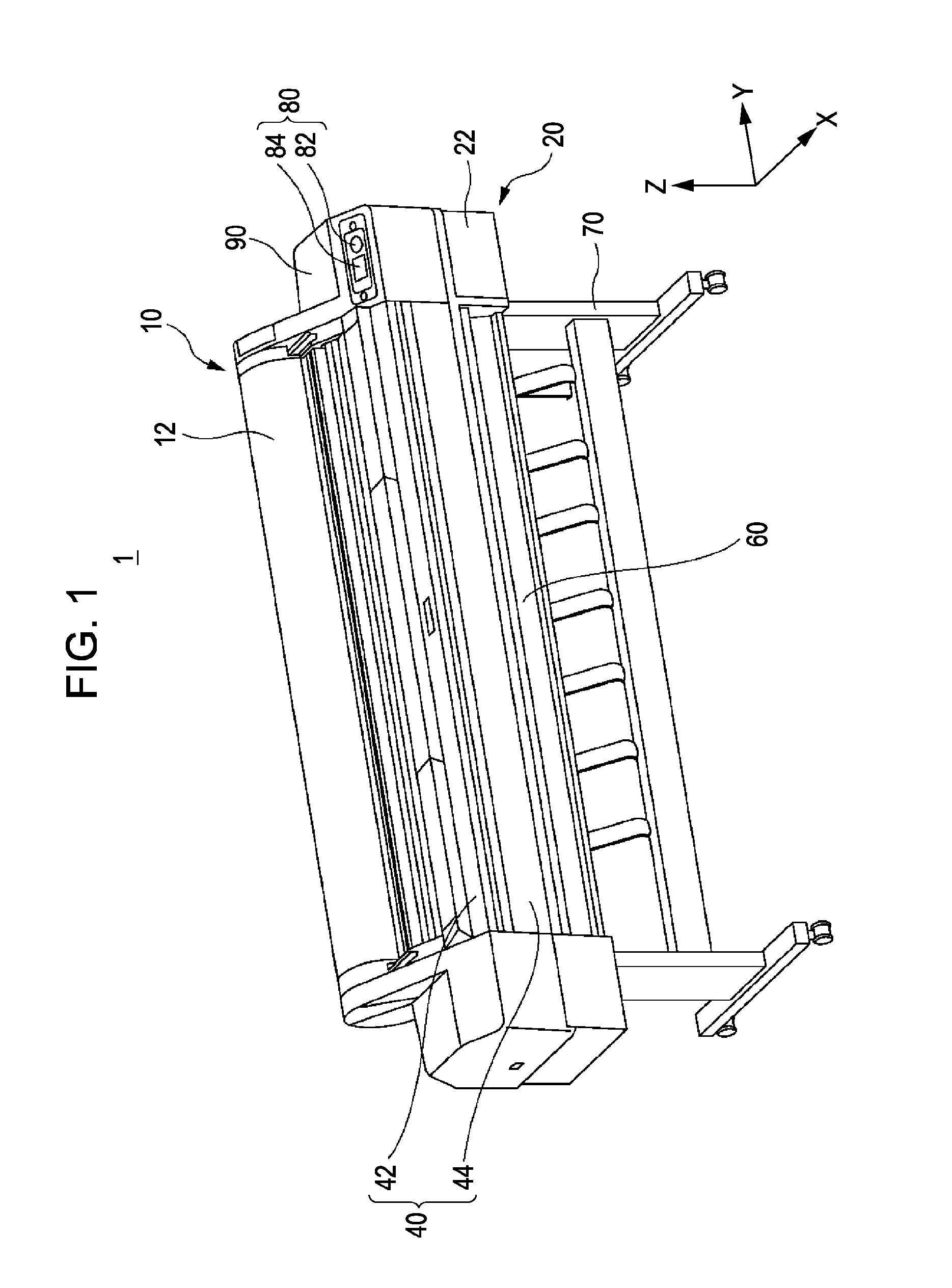
[0038]FIG. 1 is a perspective view illustrating an ink jet printer 1 according to an embodiment. As illustrated in FIG. 1, the ink jet printer 1 includes a recording portion 40, a housing 90, a loading portion 10, and leg portions 70. The recording portion 40 is arranged such that a lengthwise direction thereof is horizontal. The housing 90 is attached to an end of the recording portion 40. The loading portion 10 is attached at the upper side of the recording portion 40. The leg portions 70 support the recording portion 40 and the housing 90 from the lower side.

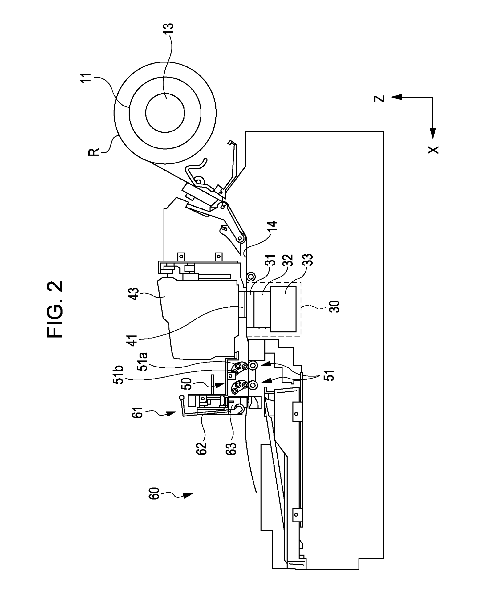
[0039]A roll assembly 11 is loaded in the loading portion 10. The roll assembly 11 includes a roll R around which a long recording target medium (see, FIG. 2, hereinafter, also referred to as “medium”) is wound in a superimposed manner. In FIG. 1, the roll assembly 11 (see, FIG. 2) is covered by a roll cover 12. An internal mechanism of the recording portion 40 is covered by a top cover 42 and a front cover 44. A head 41 (see...


PUM


Abstract

A platen unit includes a platen that has a hole for sucking a medium, a platen supporting member that has an internal space which communicates with the hole of the platen, and an elastic member that is provided between the platen and the platen supporting member, and keeps airtightness between the platen and the platen supporting member. In the platen unit, the platen is movable in an up-down direction on the elastic member.

Description

BACKGROUND[0001]1. Technical Field[0002]The present invention relates to a platen unit and a liquid ejecting apparatus.[0003]2. Related Art[0004]An ink jet printer which forms an image on a medium by ejecting ink is used. In such an ink jet printer, a platen for supporting a medium is provided. The platen supports the medium appropriately so as to keep a distance between a head which ejects ink and the medium properly.[0005]In JP-A-2010-214880 and JP-A-2000-289290, a platen for supporting a sheet at the time of printing has been disclosed. In JP-A-2009-279780, a large format printer which performs printing on a sheet having a large sheet width has been disclosed.[0006]When a medium such as a sheet is transported on a platen, the medium is ensured to be flat appropriately by being sucked by the platen, and so on, in order to keep a distance between a head and the medium to be constant. On the other hand, when the medium enters on the platen, a front end of the medium makes contact wi...

Claims


Application Information

Patent Timeline
Patent Type & Authority Patents(United States)
IPC IPC(8): B41J2/01
CPCB41J11/0085B41J11/20B41J11/06
Inventor KOIKE, YASUNORIOKADA, TOSHIYAKAWAKAMI, TAKAYUKI
Owner SEIKO EPSON CORP
Why Eureka
Try Eureka