
Surgical guide and method

a surgical guide and surgical technology, applied in the field of surgical guide and method, can solve the problems of the most difficult and skill-intensive part of the implant procedure, and the cost and complexity of the surgical work of the dental implant procedure, and affecting the healing effect of the implan

Active Publication Date: 2014-05-06
STUMPEL LAMBERT J
View PDF29 Cites 24 Cited by
  • Summary
  • Abstract
  • Description
  • Claims
  • Application Information

AI Technical Summary

Benefits of technology

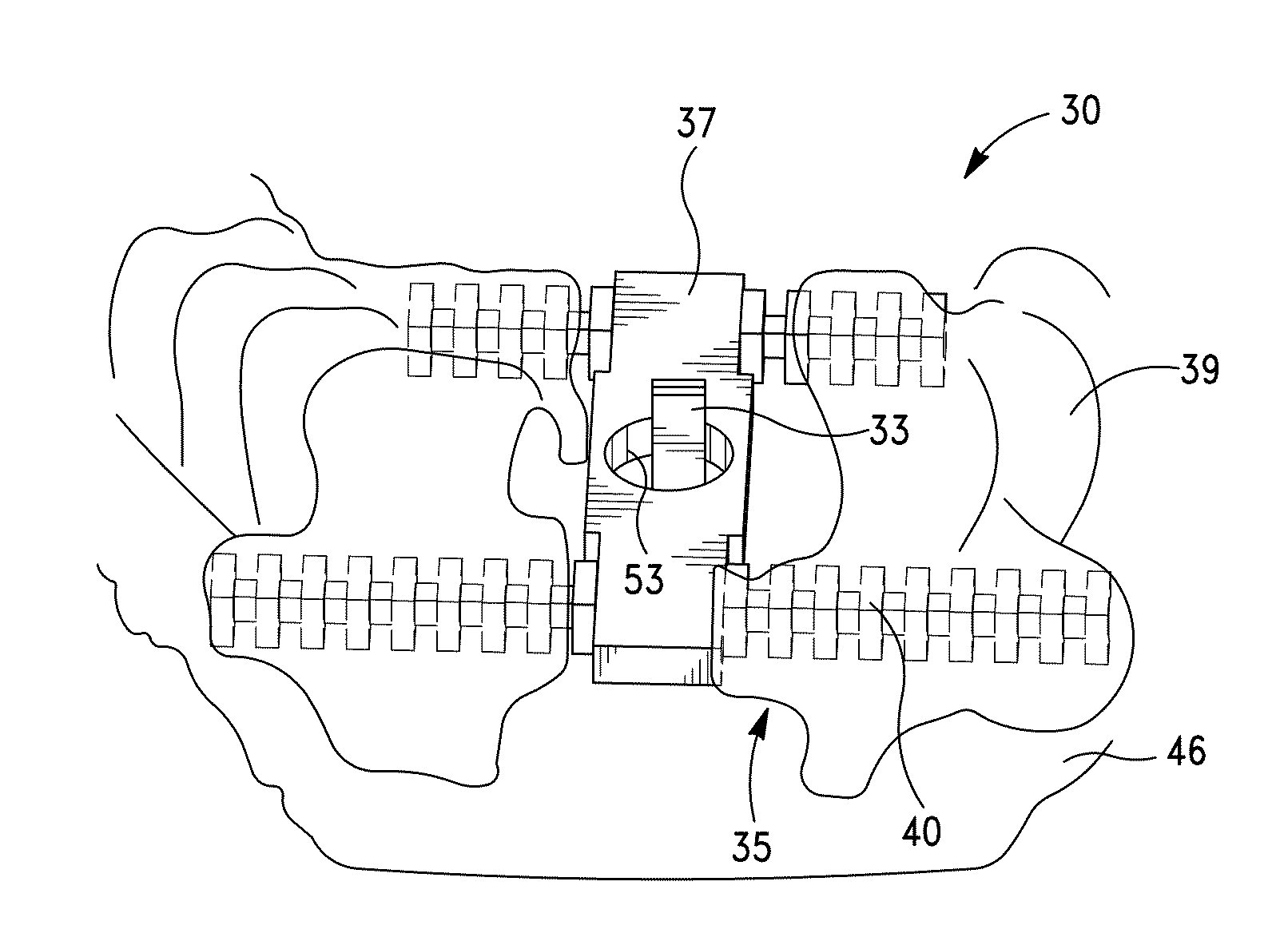
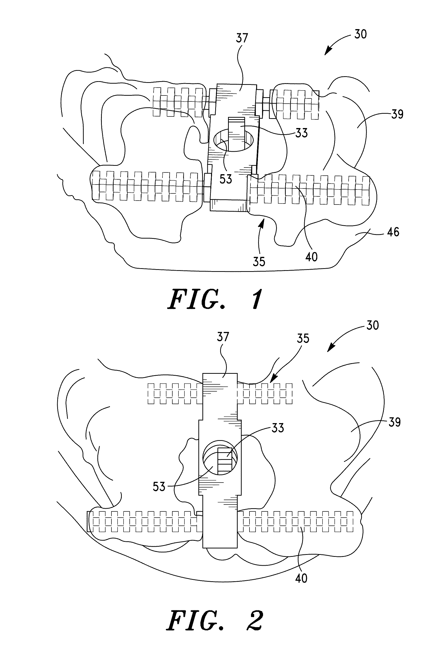
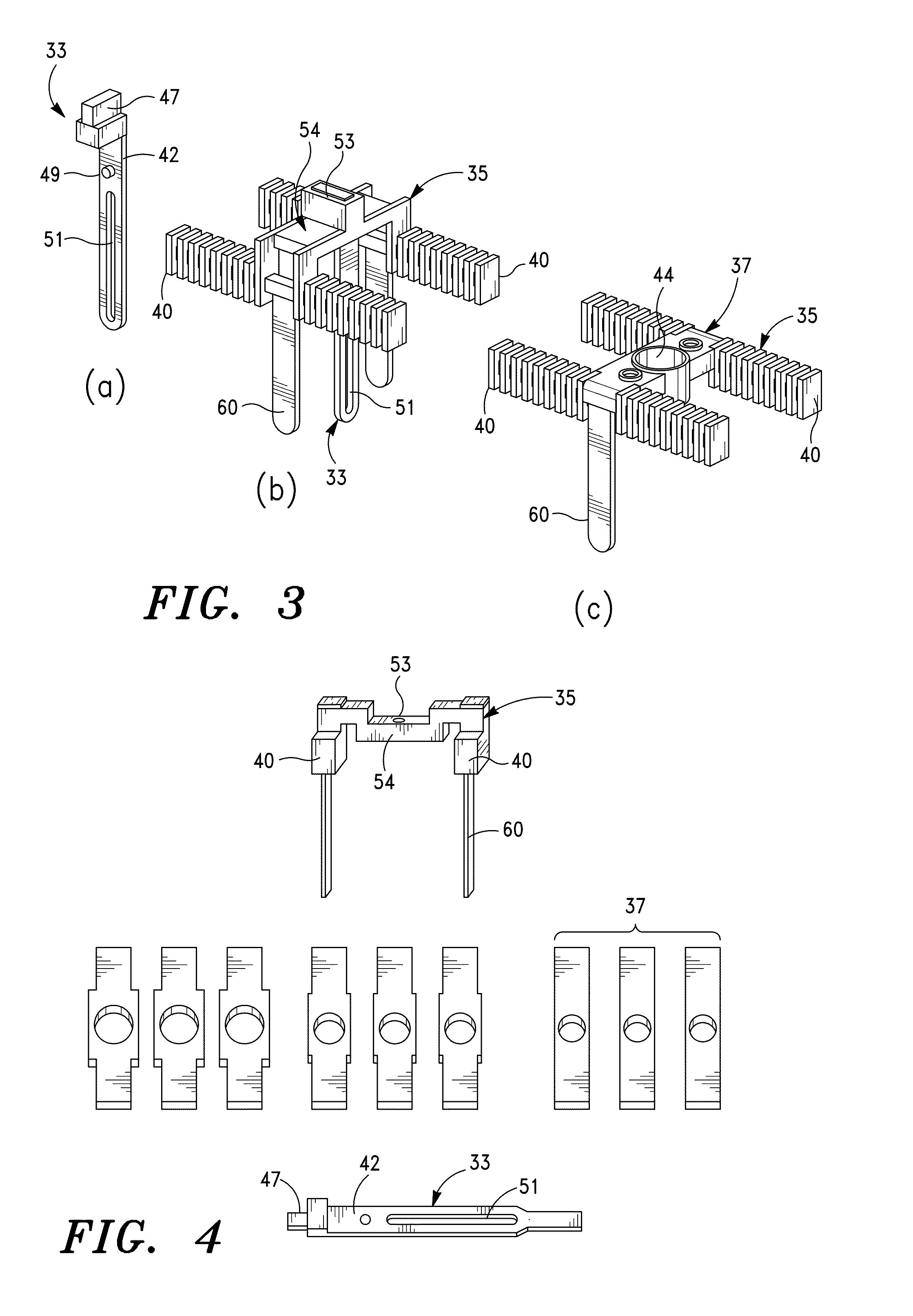
The present invention relates to a surgical guide for positioning a dental implement such as a dental tool, implant, or prosthetic. The guide is designed to be positioned on a patient's dental arch and includes a mounting assembly with a removable rotation block. The mounting assembly is designed to maintain a desired position and angle of the guide in relation to the jawbone. The guide is prepared using a computer model of the patient's dental arch and can be easily transferred to the patient for use during a dental implant procedure. The guide helps to accurately position the dental tool or implant in relation to the jawbone, which can improve the precision and safety of the procedure.

Problems solved by technology

In comparison to dentures, however, dental implant procedures involve costly and complex surgical work.
The most difficult and skill-intensive part of the implant procedure is generally positioning of the drill to create the hole in the jawbone that will receive the implant.
Inaccuracies in placing the hole can damage nearby vital structures such as nerves, blood vessels, sinus and neighboring teeth.
Improper placement of the hole for the implant presents problems for the surgeon during placement of the implant in the bone.
Even more troublesome, if bone has been mistakenly removed, new bone may have to be grafted or added to the site.
Positioning mistakes also require additional office visits by the patient, additional time to completion, and unnecessary discomfort.
Because the bone is masked under the gum tissue, and because it is difficult to fully inspect the site, the surgeon typically has great difficulty in determining the proper position in this initial step.
This method increases the risk of infection and provides further discomfort for the patient.
Free-hand drilling also presents safety hazards and accuracy problems.
Although the surgeon can initially determine where to drill, during the drilling procedure, the drill bit can “jump” or slip.
Additionally, free-hand drilling requires the surgeon to act without a complete view of the mouth interior and implant site.
Also, this method usually only allows the surgeon to practice drilling on a model and does not assist with precisely transferring or mapping the determined drilling position from the model back to the implant site in the subject patient.
Ultimately, the drilling procedure still requires a steady hand and drilling expertise.
Errors, however, still often occur when transferring the model positioning to the drill guide.
Additionally, the drill guide does not allow for controlled adjustment.
This adjustment, however, has the same limitations of free-hand adjustment because a user adjusts the guide in 3D space with little control.
Moreover, the Harter guide limits a user's ability to make adjustments to pivot angle independent of translational movement.
Adjustments to the pivot angle above the teeth results in significant translation of the point of entry of the drill bit at the jawbone below.
This adds to the difficulty of achieving accurate positioning.
Such additional steps create undesirable consequent increases in overall cost and overall procedure time.

Method used


Image

  • Surgical guide and method
  • Surgical guide and method
  • Surgical guide and method

Examples


Embodiment Construction

[0089]Reference will now be made in detail to the various embodiments of the invention, examples of which are illustrated in the accompanying drawings. While the invention will be described in conjunction with the various embodiments, it will be understood that they are not intended to limit the invention to those embodiments. On the contrary, the invention is intended to cover alternatives, modifications and equivalents, which may be included within the spirit and scope of the invention as defined by the appended claims.

[0090]In many aspects, the present invention is similar to those described in U.S. patent application Ser. No. 11 / 870,310 filed Oct. 10, 2007, entitled SURGICAL GUIDE FOR DENTAL IMPLANTS AND METHOD THEREFOR, U.S. Provisional Patent Application No. 60 / 850,605 filed Oct. 10, 2006, entitled IMPLANT POSITIONING SYSTEM MODEL BASED, and U.S. Provisional Patent Application No. 61 / 289,310 filed Dec. 22, 2009, entitled SURGICAL GUIDE, the entire contents of which application...


PUM


Abstract

A method for preparing a surgical guide for positioning of a dental implementation. The method includes positioning a positioning device relative to a model jawbone, translating the positioning device in a BL direction, adjusting a BL angle of the positioning device about a BL pivot axis corresponding to a desired position of a top of the dental implementation, and fixing the BL position, BL angle, and z-height of the positioning device. A mounting assembly mounts to the positioning device and includes a removable rotation block with a guide hole. The mounting assembly is movable in the MD direction while the BL position is fixed. A template fixes the mounting assembly for transferring the positioning information to a patient's mouth. Various aspects of the design process can be performed on a computer. The guide and a method of using the guide to perform an implant procedure are also disclosed.

Description

CROSS-REFERENCES TO RELATED APPLICATIONS[0001]This application claims priority to U.S. Provisional Patent Application No. 61 / 289,310 filed Dec. 22, 2009, entitled SURGICAL GUIDE, and to U.S. Provisional Patent Application No. 61 / 349,779 filed May 28, 2010, entitled SURGICAL GUIDE AND METHOD, the entire contents of which applications is incorporated herein for all purposes by this reference.BACKGROUND OF THE INVENTION[0002]1. Field of the Invention[0003]The present invention relates to a method of positioning a dental implant or surgical tool at a desired site. Various aspects of the present invention relate to a method of positioning a dental implant utilizing a dental model, preparing a surgical guide, using the surgical guide to perform an osteotomy and align a dental implant, and intra-oral placement of the dental implant. Various aspects of the present invention relate to a surgical guide for accurately determining a position for an implant and translating a position on a model ...

Claims


Application Information

Patent Timeline
Patent Type & Authority Patents(United States)
IPC IPC(8): A61C3/02
CPCA61C8/009A61C8/0089G06F17/5086A61C1/084B33Y80/00G06F30/17
Inventor STUMPEL, LAMBERT, J.
Owner STUMPEL LAMBERT J
Learn More