
Solar powered devices using location-based energy control and method for operation of solar powered devices

a technology of solar energy control and solar energy, applied in the direction of parallel operation of dc sources, instruments, transportation and packaging, etc., can solve the problems of system depletion of power level, reducing system effectiveness, and unable to maintain the programmed level of illumination, so as to prevent critical failure of the device

Inactive Publication Date: 2014-05-06
CARMANAH TECHNOLOGIES INC
View PDF13 Cites 4 Cited by
  • Summary
  • Abstract
  • Description
  • Claims
  • Application Information

AI Technical Summary

Benefits of technology

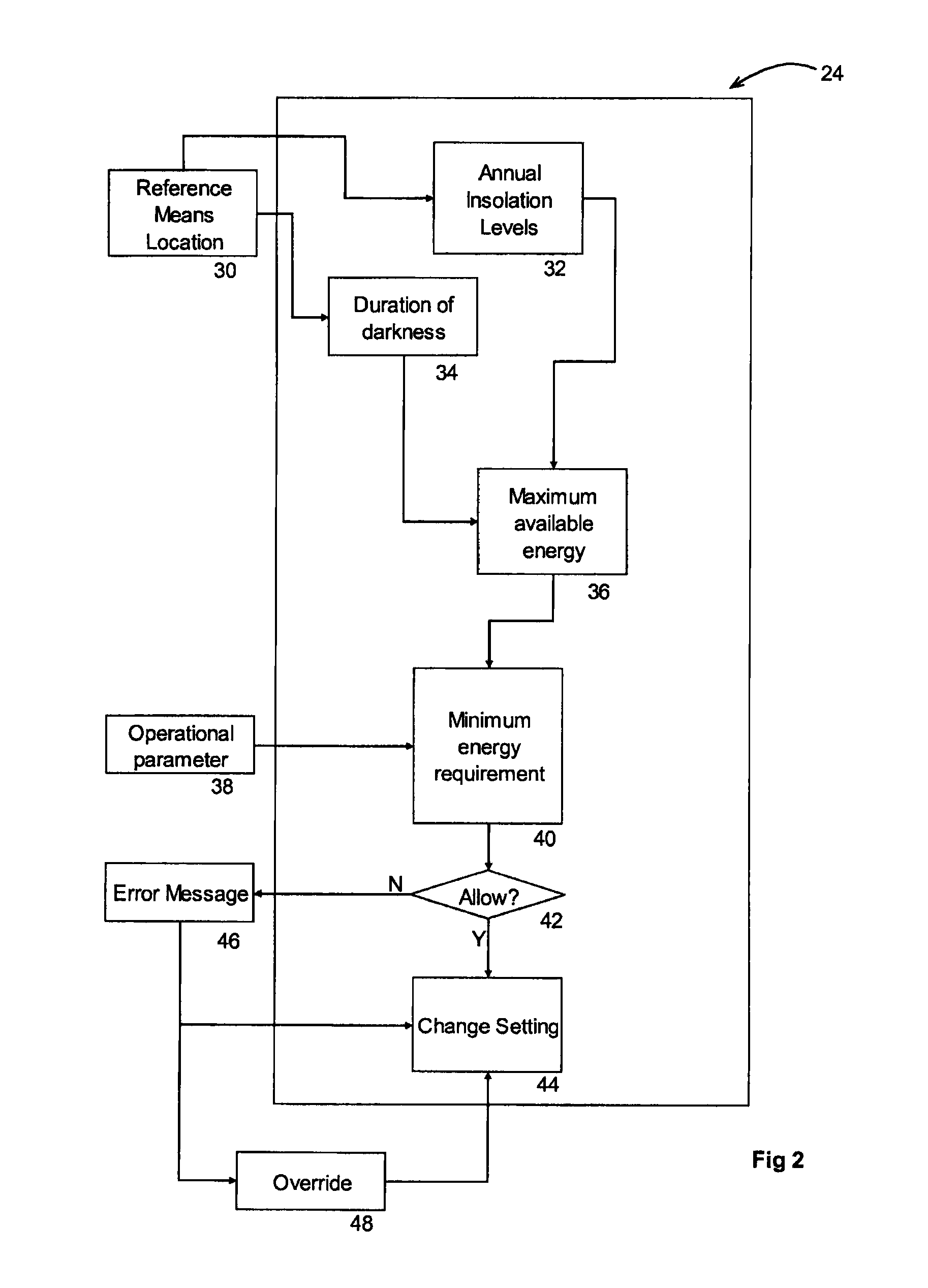
[0016]Once the device knows its location, along with the amount of solar energy that might be expected throughout the year, the device restricts the combinations of operational parameters for the device to those that can be sustained by the amount of solar energy available in that location. This assists in preventing critical failures of the device due to unreasonable energy demands.

Problems solved by technology

Accordingly, a solar powered light optimized for Los Angeles may not work for certain applications in Seattle.
However, in areas where less light than anticipated is available, or where the dark time is longer than anticipated, the system could deplete its power level and be unable to maintain the programmed level of illumination.
Further, there is no assurance that the computed maximum level of illumination will meet the minimum level of illumination required by the installer, decreasing the effectiveness of the system once available power levels begin to drop.
However, neither patent teaches any means to ensure that a minimum level of sunlight required by the installer is available at any given time.
It is therefore not certain that sufficient solar power would be available to operate the devices during the life cycle of the devices.
However, there is no information relating to the process followed by the control module if the user has set goals that the system is incapable of reaching, given the environmental factors at the system's geographic location.
Again, this method does not contemplate situations where sufficient power to meet the various demands of the installer can not be generated.
However, minimal guidance is often provided or accepted to assist the installer in calculating and implementing the optimal configuration.
As a result, an installer may configure a device to desired parameters for his particular application, only to find that the device does not have enough energy to operate as instructed.
This results in user frustration.
However, because there is no means to verify that adequate sunlight will be available, the patent also teaches that the solar generator preferably includes several extra photoelectric cells, in order to ensure that sufficient solar energy may be gathered to power the apparatus.

Method used


Image

  • Solar powered devices using location-based energy control and method for operation of solar powered devices
  • Solar powered devices using location-based energy control and method for operation of solar powered devices
  • Solar powered devices using location-based energy control and method for operation of solar powered devices

Examples


Embodiment Construction

[0035]The solar powered device is illustrated in the present application as a solar powered lighting device, but the principles of the invention are applicable to any solar powered device, such as solar powered signage.

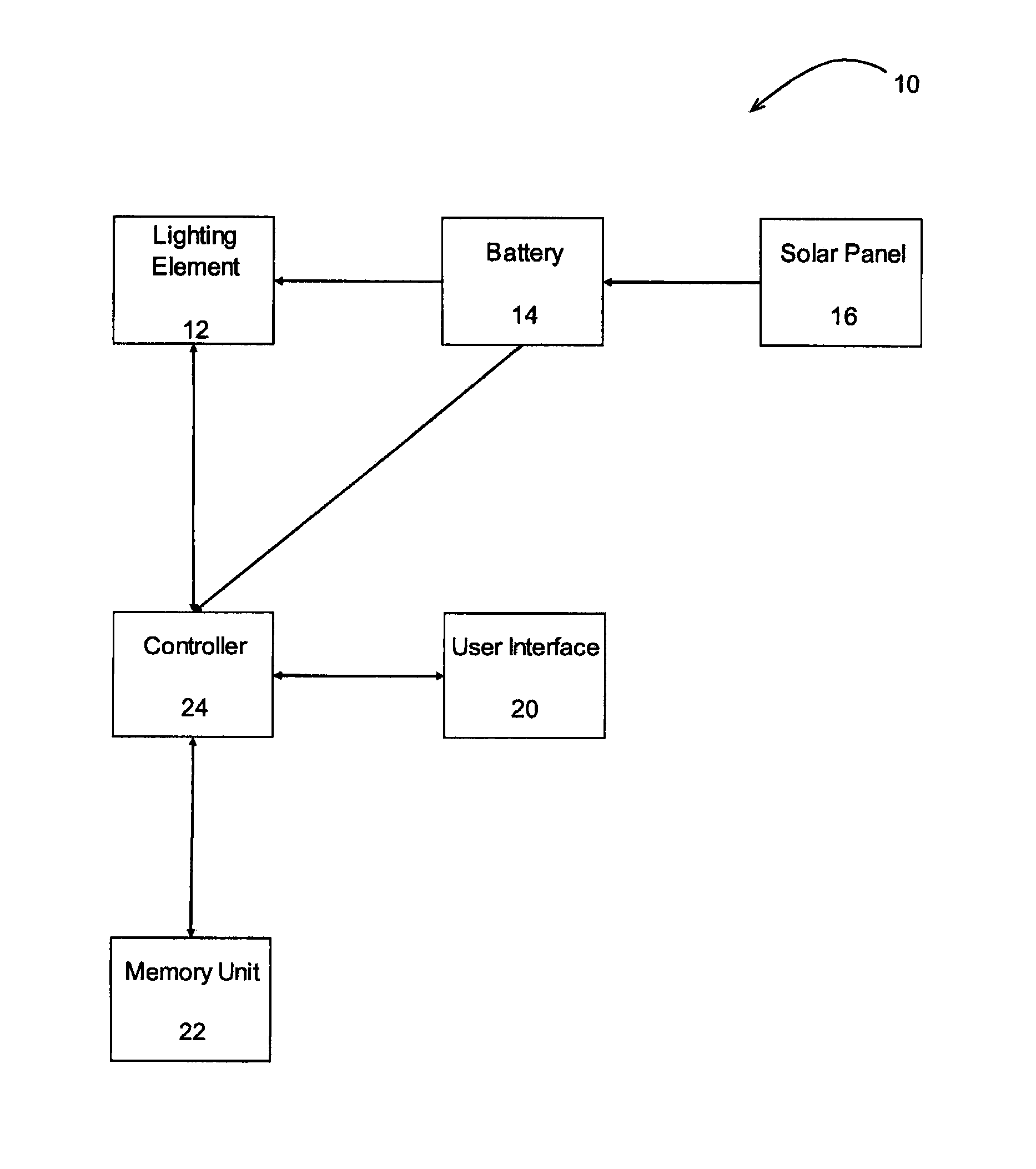
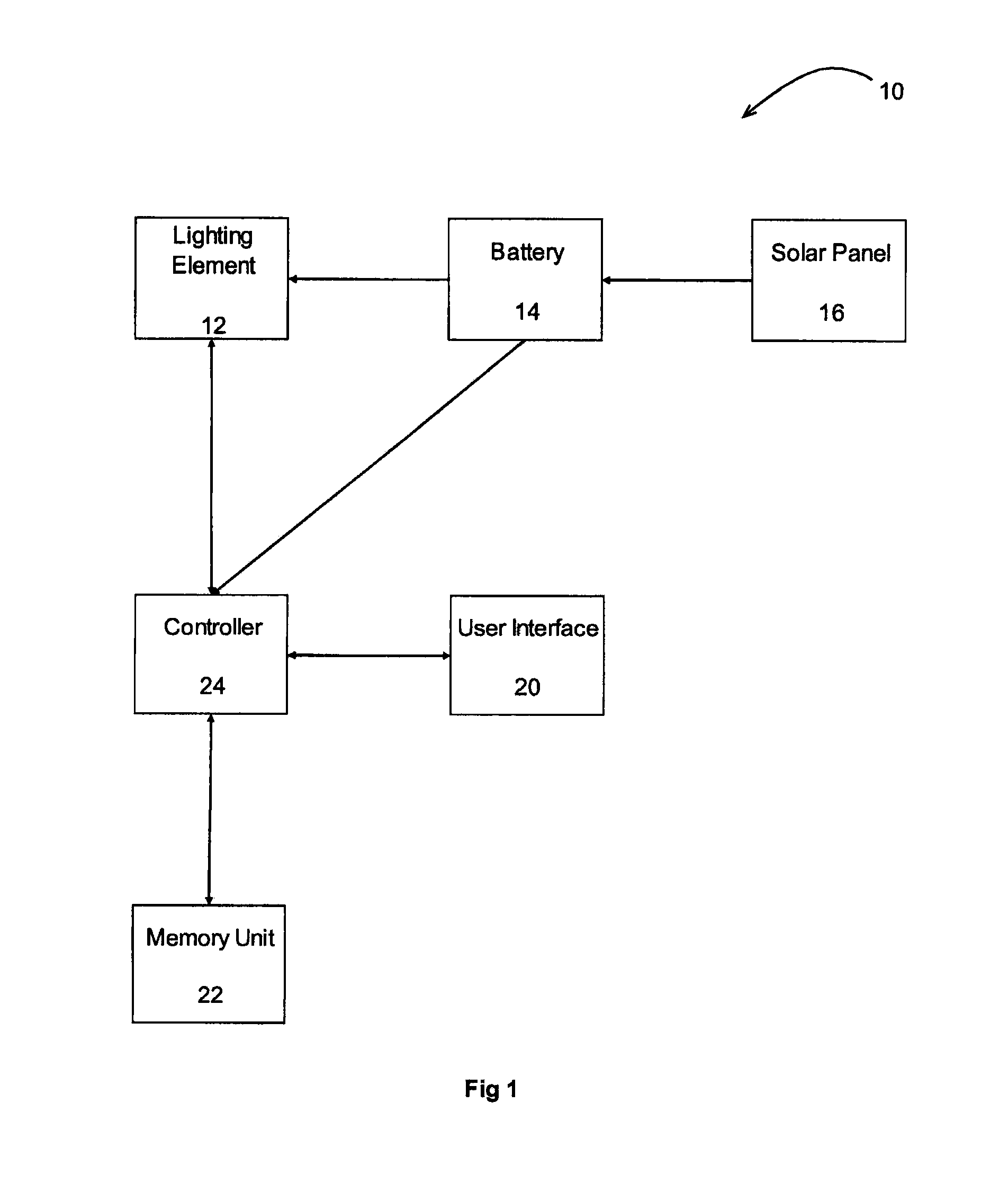
[0036]Referring to FIG. 1, the solar powered device 10 comprises at least one lighting element, such as a beacon lamp 12, powered by at least one rechargeable battery 14. Lighting element 12 may be a light emitting diode (LED) or any other suitable light element capable of providing the required light intensity and durability for the solar powered device specifications. The battery 14 receives power from a solar panel 16 which converts solar energy into electrical energy that can be stored by the battery 14. The device 10 further comprises a user interface 20, through which a user may enter a set of one or more desired operating parameters upon installation, or may change one or more parameters during the lifetime of the device 10. The device 10 further comprises a me...


PUM


Abstract

A solar powered device and a method of operating such a device to allow it to receive and store information about its physical location, from which it can determine the minimum expected solar energy levels that will be available to it. Based on the minimum expected levels, the device then limits its configurable settings to preferably enable only those configurations having maximum energy demands that can be met or exceeded by the minimum expected energy levels.

Description

FIELD OF THE INVENTION[0001]This invention relates to solar powered devices that can be configured for optimal use based on the geographic location of the device and the solar environment associated with that location, and a method for operating such devices.BACKGROUND OF THE INVENTION[0002]Solar powered products often include a means of configuring their energy consumption based on battery and battery charge parameters. This allows the energy consumption of the device to be matched with the amount of solar energy the device receives and stores, maximizing the performance of the device for a given location and preventing failure of the device at a critical time.[0003]For example, a solar powered light may have an adjustable light intensity, which is generally set as a percentage of the light's maximum brightness. A second configurable parameter is the flash pattern, which is generally set as a given number of illuminations in a specified period of time. It is important that the ligh...

Claims


Application Information

Patent Timeline
Patent Type & Authority Patents(United States)
IPC IPC(8): G08B21/00
CPCY02B20/42H05B37/0281H05B37/0227Y10T307/50H05B47/115H05B47/16Y02B20/40
Inventor LOCKWOOD, AARON, JOHN
Owner CARMANAH TECHNOLOGIES INC
Learn More